Intel S2600CP Technical Product Specification - Page 164
Residual Voltage Immunity in Standby mode, 3.4.8, Common Mode Noise, 3.4.9, Hot Swap
 |
View all Intel S2600CP manuals
Add to My Manuals
Save this manual to your list of manuals |
Page 164 highlights
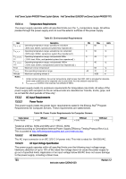
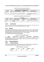
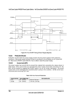
Intel® Server System P4000CP Power System Options Intel® Server Board S2600CP and Server System P4000CP TPS 13.3.4.7 Residual Voltage Immunity in Standby mode The power supply is immune to any residual voltage placed on its outputs (Typically a leakage voltage through the system from standby output) up to 500mV. There is neither additional heat generated, nor stressing of any internal components with this voltage applied to any individual or all outputs simultaneously. It also does not trip the protection circuits during turn on. The residual voltage at the power supply outputs for no load condition does not exceed 100mV when AC voltage is applied and the PSON# signal is de-asserted. 13.3.4.8 Common Mode Noise The Common Mode noise on any output does not exceed 350mV pk-pk over the frequency band of 10Hz to 20MHz. The measurement is made across a 100Ω resistor between each of DC outputs, including ground at the DC power connector and chassis ground (power subsystem enclosure). The test set-up shall use a FET probe such as Tektronix model P6046 or equivalent. 13.3.4.9 Hot Swap Requirements Hot swapping a power supply is the process of inserting and extracting a power supply from an operating power system. During this process the output voltages remains within the limits with the capacitive load specified. The hot swap test is conducted when the system is operating under static, dynamic, and zero loading conditions. The power supply uses a latching mechanism to prevent insertion and extraction of the power supply when the AC power cord is inserted into the power supply. 13.3.4.10 Forced Load Sharing The +12V output will have active load sharing. The output will share within 10% at full load. The failure of a power supply does not affect the load sharing or output voltages of the other supplies still operating. The supplies are able to load share in parallel and operate in a hotswap/redundant 1+1 configurations. The 12VSB output is not required to actively share current between power supplies (passive sharing). The 12VSB output of the power supplies are connected together in the system so that a failure or hot swap of a redundant power supply does not cause these outputs to go out of regulation in the system. 13.3.4.11 Ripple/Noise The maximum allowed ripple/noise output of the power supply is defined in below Table. 41. This is measured over a bandwidth of 10Hz to 20MHz at the power supply output connectors. A 10F tantalum capacitor in parallel with a 0.1F ceramic capacitor is placed at the point of measurement. Table 104. Ripples and Noise +12V main 120mVp-p The test set-up shall be as shown below. +12VSB 120mVp-p 148 Revision 1.2 Intel order number G26942-003
-
 1
1 -
2
-
3
-
4
-
5
-
6
-
7
-
8
-
9
-
10
-
11
-
12
-
13
-
14
-
15
-
16
-
17
-
18
-
19
-
20
-
21
-
22
-
23
-
24
-
25
-
26
-
27
-
28
-
29
-
30
-
31
-
32
-
33
-
34
-
35
-
36
-
37
-
38
-
39
-
40
-
41
-
42
-
43
-
44
-
45
-
46
-
47
-
48
-
49
-
50
-
51
-
52
-
53
-
54
-
55
-
56
-
57
-
58
-
59
-
60
-
61
-
62
-
63
-
64
-
65
-
66
-
67
-
68
-
69
-
70
-
71
-
72
-
73
-
74
-
75
-
76
-
77
-
78
-
79
-
80
-
81
-
82
-
83
-
84
-
85
-
86
-
87
-
88
-
89
-
90
-
91
-
92
-
93
-
94
-
95
-
96
-
97
-
98
-
99
-
100
-
101
-
102
-
103
-
104
-
105
-
106
-
107
-
108
-
109
-
110
-
111
-
112
-
113
-
114
-
115
-
116
-
117
-
118
-
119
-
120
-
121
-
122
-
123
-
124
-
125
-
126
-
127
-
128
-
129
-
130
-
131
-
132
-
133
-
134
-
135
-
136
-
137
-
138
-
139
-
140
-
141
-
142
-
143
-
144
-
145
-
146
-
147
-
148
-
149
-
150
-
151
-
152
-
153
-
154
-
155
-
156
-
157
-
158
-
 159
159 -
 160
160 -
 161
161 -
 162
162 -
 163
163 -
 164
164 -
 165
165 -
 166
166 -
 167
167 -
 168
168 -
 169
169 -
170
-
171
-
172
-
173
-
174
-
175
-
176
-
177
-
178
-
179
-
180
-
181
-
182
-
183
-
184
-
185
-
186
-
187
-
188
-
189
-
190
-
191
-
192
-
193
-
194
-
195
-
196
-
197
-
198
-
199
-
200
-
201
-
202
-
203
-
204
-
205
-
206
-
207
-
208
-
209
-
210
-
211
-
212
-
213
-
214
-
215
-
216
-
217
-
218
-
219
-
220
-
221
-
222
-
223
-
224
-
225
-
226
-
227
-
228
 |
 |