Intel S2600CP Technical Product Specification - Page 169
Higer Power Common Redundant Power Distribution Board PDB
 |
View all Intel S2600CP manuals
Add to My Manuals
Save this manual to your list of manuals |
Page 169 highlights
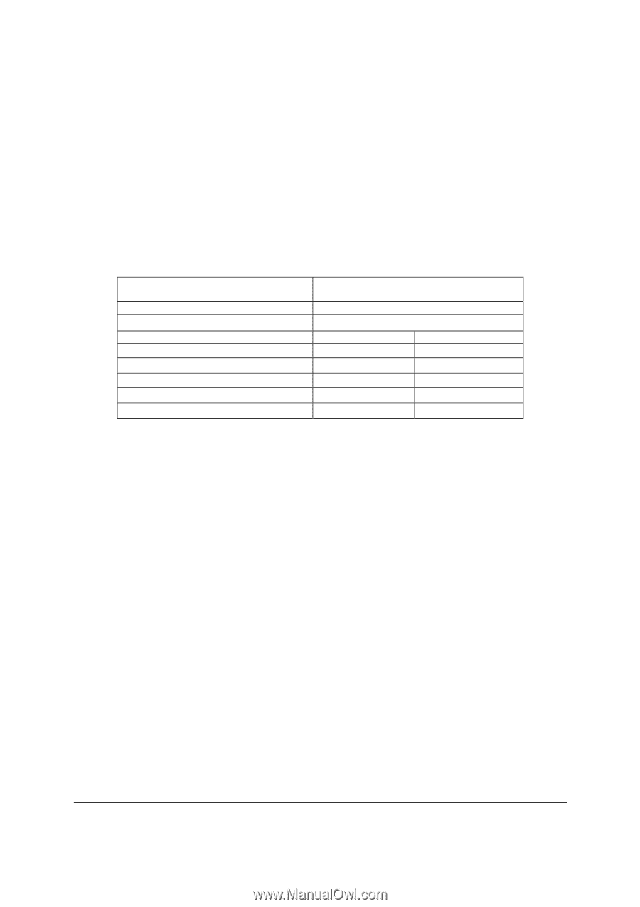
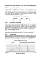
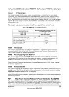
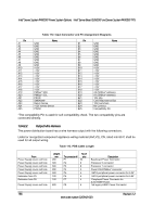
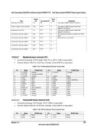
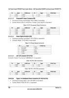
Intel® Server Board S2600CP and Server System P4000CP TPS Intel® Server System P4000CP Power System Options 13.3.6.3 SMBAlert# Signal This signal indicates that the power supply is experiencing a problem that the user should investigate. This shall be asserted due to Critical events or Warning events. The signal shall activate in the case of critical component temperature reached a warning threshold (see sec. 4.10), general failure, over-current, over-voltage, under-voltage, failed fan. This signal may also indicate the power supply is reaching its end of life or is operating in an environment exceeding the specified limits. This signal is to be asserted in parallel with LED turning solid Amber or blink Amber. Table 110. SMBAlert# Signal Characteristics Signal Type (Active Low) Alert# = High Alert# = Low Logic level low voltage, Isink=4 mA Logic level high voltage, Isink=50 A Sink current, Alert# = low Sink current, Alert# = high Alert# rise and fall time Open collector/drain output from power supply. Pullup to VSB located in system. OK Power Alert to system MIN 0 V MAX 0.4 V 3.46 V 4 mA 50 A 100 s 13.3.7 Thermal CLST The power supply shall assert the SMBAlert signal when a temperature sensor crosses a warning threshold. Refer to the Intel® Common Hardware and Firmware Requirements for CRPS Power Supplier for detailed requirements. 13.3.8 Power Supply Diagnostic "Black Box" The power supply saves the latest PMBus* data and other pertinent data into nonvolatile memory when a critical event shuts down the power supply. This data is accessible by the SMBus* interface with an external source providing power to the 12Vstby output. Refer to the Intel "Common Hardware and Firmware Requirements for CRPS Power Supplier" for detailed requirements. 13.3.9 Firmware Uploader The power supply has the capability to update its firmware by the PMBus* interface while it is in standby mode. This FW can be updated when in the system and in standby mode and outside the system with power applied to the 12Vstby pins. Refer to the Intel Common Hardware and Firmware Requirements for CRPS Power Supplier for detailed requirements. 13.4 Higer Power Common Redundant Power Distribution Board (PDB) The Power Distribution Board (PDB) for lntel® Server Chassis P4000M supports the Common Redundant power supply in a 1+1 redundant configuration. The PDB is designed to plug directly to the output connector of the PS and it contains 3 DC/DC power converters to produce other Revision 1.2 153 Intel order number G26942-003
-
 1
1 -
2
-
3
-
4
-
5
-
6
-
7
-
8
-
9
-
10
-
11
-
12
-
13
-
14
-
15
-
16
-
17
-
18
-
19
-
20
-
21
-
22
-
23
-
24
-
25
-
26
-
27
-
28
-
29
-
30
-
31
-
32
-
33
-
34
-
35
-
36
-
37
-
38
-
39
-
40
-
41
-
42
-
43
-
44
-
45
-
46
-
47
-
48
-
49
-
50
-
51
-
52
-
53
-
54
-
55
-
56
-
57
-
58
-
59
-
60
-
61
-
62
-
63
-
64
-
65
-
66
-
67
-
68
-
69
-
70
-
71
-
72
-
73
-
74
-
75
-
76
-
77
-
78
-
79
-
80
-
81
-
82
-
83
-
84
-
85
-
86
-
87
-
88
-
89
-
90
-
91
-
92
-
93
-
94
-
95
-
96
-
97
-
98
-
99
-
100
-
101
-
102
-
103
-
104
-
105
-
106
-
107
-
108
-
109
-
110
-
111
-
112
-
113
-
114
-
115
-
116
-
117
-
118
-
119
-
120
-
121
-
122
-
123
-
124
-
125
-
126
-
127
-
128
-
129
-
130
-
131
-
132
-
133
-
134
-
135
-
136
-
137
-
138
-
139
-
140
-
141
-
142
-
143
-
144
-
145
-
146
-
147
-
148
-
149
-
150
-
151
-
152
-
153
-
154
-
155
-
156
-
157
-
158
-
159
-
160
-
161
-
162
-
163
-
 164
164 -
 165
165 -
 166
166 -
 167
167 -
 168
168 -
 169
169 -
 170
170 -
 171
171 -
 172
172 -
 173
173 -
 174
174 -
175
-
176
-
177
-
178
-
179
-
180
-
181
-
182
-
183
-
184
-
185
-
186
-
187
-
188
-
189
-
190
-
191
-
192
-
193
-
194
-
195
-
196
-
197
-
198
-
199
-
200
-
201
-
202
-
203
-
204
-
205
-
206
-
207
-
208
-
209
-
210
-
211
-
212
-
213
-
214
-
215
-
216
-
217
-
218
-
219
-
220
-
221
-
222
-
223
-
224
-
225
-
226
-
227
-
228
 |
 |