Intel S2600CP Technical Product Specification - Page 53
Independent Channel Mode, 2.2.4.2, Rank Sparing Mode, 2.2.4.3, Mirrored Channel Mode, 2.2.4
 |
View all Intel S2600CP manuals
Add to My Manuals
Save this manual to your list of manuals |
Page 53 highlights
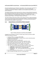
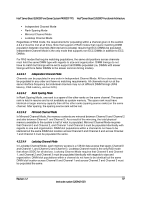
Intel® Server Board S2600CP and Server System P4000CP TPS Intel® Server Board S2600CP Functional Architecture Independent Channel Mode Rank Sparing Mode Mirrored Channel Mode Lockstep Channel Mode Regardless of RAS mode, the requirements for populating within a channel given in the section 4.2.2.2 must be met at all times. Note that support of RAS modes that require matching DIMM population between channels (Mirrored and Lockstep) require that ECC DIMMs be populated. Independent Channel Mode is the only mode that supports non-ECC DIMMs in addition to ECC DIMMs. For RAS modes that require matching populations, the same slot positions across channels must hold the same DIMM type with regards to size and organization. DIMM timings do not have to match but timings will be set to support all DIMMs populated (i.e, DIMMs with slower timings will force faster DIMMs to the slower common timing modes). 4.2.2.4.1 Independent Channel Mode Channels can be populated in any order in Independent Channel Mode. All four channels may be populated in any order and have no matching requirements. All channels must run at the same interface frequency but individual channels may run at different DIMM timings (RAS latency, CAS Latency, and so forth). 4.2.2.4.2 Rank Sparing Mode In Rank Sparing Mode, one rank is a spare of the other ranks on the same channel. The spare rank is held in reserve and is not available as system memory. The spare rank must have identical or larger memory capacity than all the other ranks (sparing source ranks) on the same channel. After sparing, the sparing source rank will be lost. 4.2.2.4.3 Mirrored Channel Mode In Mirrored Channel Mode, the memory contents are mirrored between Channel 0 and Channel 2 and also between Channel 1 and Channel 3. As a result of the mirroring, the total physical memory available to the system is half of what is populated. Mirrored Channel Mode requires that Channel 0 and Channel 2, and Channel 1 and Channel 3 must be populated identically with regards to size and organization. DIMM slot populations within a channel do not have to be identical but the same DIMM slot location across Channel 0 and Channel 2 and across Channel 1 and Channel 3 must be populated the same. 4.2.2.4.4 Lockstep Channel Mode In Lockstep Channel Mode, each memory access is a 128-bit data access that spans Channel 0 and Channel 1, and Channel 2 and Channel 3. Lockstep Channel mode is the only RAS mode that allows SDDC for x8 devices. Lockstep Channel Mode requires that Channel 0 and Channel 1, and Channel 2 and Channel 3 must be populated identically with regards to size and organization. DIMM slot populations within a channel do not have to be identical but the same DIMM slot location across Channel 0 and Channel 1 and across Channel 2 and Channel 3 must be populated the same. Revision 1.2 37 Intel order number G26942-003
-
 1
1 -
2
-
3
-
4
-
5
-
6
-
7
-
8
-
9
-
10
-
11
-
12
-
13
-
14
-
15
-
16
-
17
-
18
-
19
-
20
-
21
-
22
-
23
-
24
-
25
-
26
-
27
-
28
-
29
-
30
-
31
-
32
-
33
-
34
-
35
-
36
-
37
-
38
-
39
-
40
-
41
-
42
-
43
-
44
-
45
-
46
-
47
-
 48
48 -
 49
49 -
 50
50 -
 51
51 -
 52
52 -
 53
53 -
 54
54 -
 55
55 -
 56
56 -
 57
57 -
 58
58 -
59
-
60
-
61
-
62
-
63
-
64
-
65
-
66
-
67
-
68
-
69
-
70
-
71
-
72
-
73
-
74
-
75
-
76
-
77
-
78
-
79
-
80
-
81
-
82
-
83
-
84
-
85
-
86
-
87
-
88
-
89
-
90
-
91
-
92
-
93
-
94
-
95
-
96
-
97
-
98
-
99
-
100
-
101
-
102
-
103
-
104
-
105
-
106
-
107
-
108
-
109
-
110
-
111
-
112
-
113
-
114
-
115
-
116
-
117
-
118
-
119
-
120
-
121
-
122
-
123
-
124
-
125
-
126
-
127
-
128
-
129
-
130
-
131
-
132
-
133
-
134
-
135
-
136
-
137
-
138
-
139
-
140
-
141
-
142
-
143
-
144
-
145
-
146
-
147
-
148
-
149
-
150
-
151
-
152
-
153
-
154
-
155
-
156
-
157
-
158
-
159
-
160
-
161
-
162
-
163
-
164
-
165
-
166
-
167
-
168
-
169
-
170
-
171
-
172
-
173
-
174
-
175
-
176
-
177
-
178
-
179
-
180
-
181
-
182
-
183
-
184
-
185
-
186
-
187
-
188
-
189
-
190
-
191
-
192
-
193
-
194
-
195
-
196
-
197
-
198
-
199
-
200
-
201
-
202
-
203
-
204
-
205
-
206
-
207
-
208
-
209
-
210
-
211
-
212
-
213
-
214
-
215
-
216
-
217
-
218
-
219
-
220
-
221
-
222
-
223
-
224
-
225
-
226
-
227
-
228
 |
 |