Intel S2600CP Technical Product Specification - Page 81
Sensor Monitoring
 |
View all Intel S2600CP manuals
Add to My Manuals
Save this manual to your list of manuals |
Page 81 highlights
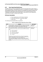
Intel® Server Board S2600CP and Server System P4000CP TPS Intel® Server Board S2600CP and Intel® Server System P4000CP Platform Management FW logs a SEL event indicating that a watchdog-generated BMC reset (either soft or hard reset) has occurred. This event may be logged after the actual reset has occurred. Refer sensor section for details for the related sensor definition. The BMC will also indicate a degraded system status on the Front Panel Status LED after an BMC HW reset or FW stack reset. This state (which follows the state of the associated sensor) will be cleared upon system reset or (AC or DC) power cycle. Note: A reset of the BMC may result in the following system degradations that will require a system reset or power cycle to correct: 1. Timeout value for the rotation period can be set using this parameterPotentially incorrect ACPI Power State reported by the BMC. 2. Reversion of temporary test modes for the BMC back to normal operational modes. 3. FP status LED and DIMM fault LEDs may not reflect BIOS detected errors. 6.3 Sensor Monitoring 6.3.1 Overview The BMC monitors system hardware and reports system health. The information gathered from physical sensors is translated into IPMI sensors as part of the "IPMI Sensor Model". The BMC also reports various system state changes by maintaining virtual sensors that are not specifically tied to physical hardware. This section describes the BMC sensors as well as describing how specific sensor types are modeled. Unless otherwise specified, the term "sensor" refers to the IPMI sensor-model definition of a sensor. 6.3.2 Core Sensors Specific server boards may only implement a sub-set of sensors and/or may include additional sensors. The system-specific details of supported sensors and events are described in the Appendix of this document. The actual sensor name associated with a sensor number may vary between server boards or systems. Sensor Type Codes Sensor table given below lists the sensor identification numbers and information regarding the sensor type, name, supported thresholds, assertion and de-assertion information, and a brief description of the sensor purpose. Refer to the Intelligent Platform Management Interface Specification, Version 2.0 for sensor and event/reading-type table information. 1. Sensor Type The sensor type references the values in the Sensor Type Codes table in the Intelligent Platform Management Interface Specification Second Generation, Version 2.0. It provides a context to interpret the sensor. 2. Event/Reading Type The event/reading type references values from the Event/Reading Type Code Ranges and the Generic Event/Reading Type Code tables in the Intelligent Platform Management Interface Specification Second Generation, Version 2.0. Digital sensors are specific type of discrete sensors that only have two states. 3. Event Thresholds/Triggers The following event thresholds are supported for threshold type sensors: Revision 1.2 65 Intel order number G26942-003
-
 1
1 -
2
-
3
-
4
-
5
-
6
-
7
-
8
-
9
-
10
-
11
-
12
-
13
-
14
-
15
-
16
-
17
-
18
-
19
-
20
-
21
-
22
-
23
-
24
-
25
-
26
-
27
-
28
-
29
-
30
-
31
-
32
-
33
-
34
-
35
-
36
-
37
-
38
-
39
-
40
-
41
-
42
-
43
-
44
-
45
-
46
-
47
-
48
-
49
-
50
-
51
-
52
-
53
-
54
-
55
-
56
-
57
-
58
-
59
-
60
-
61
-
62
-
63
-
64
-
65
-
66
-
67
-
68
-
69
-
70
-
71
-
72
-
73
-
74
-
75
-
 76
76 -
 77
77 -
 78
78 -
 79
79 -
 80
80 -
 81
81 -
 82
82 -
 83
83 -
 84
84 -
 85
85 -
 86
86 -
87
-
88
-
89
-
90
-
91
-
92
-
93
-
94
-
95
-
96
-
97
-
98
-
99
-
100
-
101
-
102
-
103
-
104
-
105
-
106
-
107
-
108
-
109
-
110
-
111
-
112
-
113
-
114
-
115
-
116
-
117
-
118
-
119
-
120
-
121
-
122
-
123
-
124
-
125
-
126
-
127
-
128
-
129
-
130
-
131
-
132
-
133
-
134
-
135
-
136
-
137
-
138
-
139
-
140
-
141
-
142
-
143
-
144
-
145
-
146
-
147
-
148
-
149
-
150
-
151
-
152
-
153
-
154
-
155
-
156
-
157
-
158
-
159
-
160
-
161
-
162
-
163
-
164
-
165
-
166
-
167
-
168
-
169
-
170
-
171
-
172
-
173
-
174
-
175
-
176
-
177
-
178
-
179
-
180
-
181
-
182
-
183
-
184
-
185
-
186
-
187
-
188
-
189
-
190
-
191
-
192
-
193
-
194
-
195
-
196
-
197
-
198
-
199
-
200
-
201
-
202
-
203
-
204
-
205
-
206
-
207
-
208
-
209
-
210
-
211
-
212
-
213
-
214
-
215
-
216
-
217
-
218
-
219
-
220
-
221
-
222
-
223
-
224
-
225
-
226
-
227
-
228
 |
 |