Yamaha AW4416 Reference Guide - Page 23
Patch OUT
 |
View all Yamaha AW4416 manuals
Add to My Manuals
Save this manual to your list of manuals |
Page 23 highlights
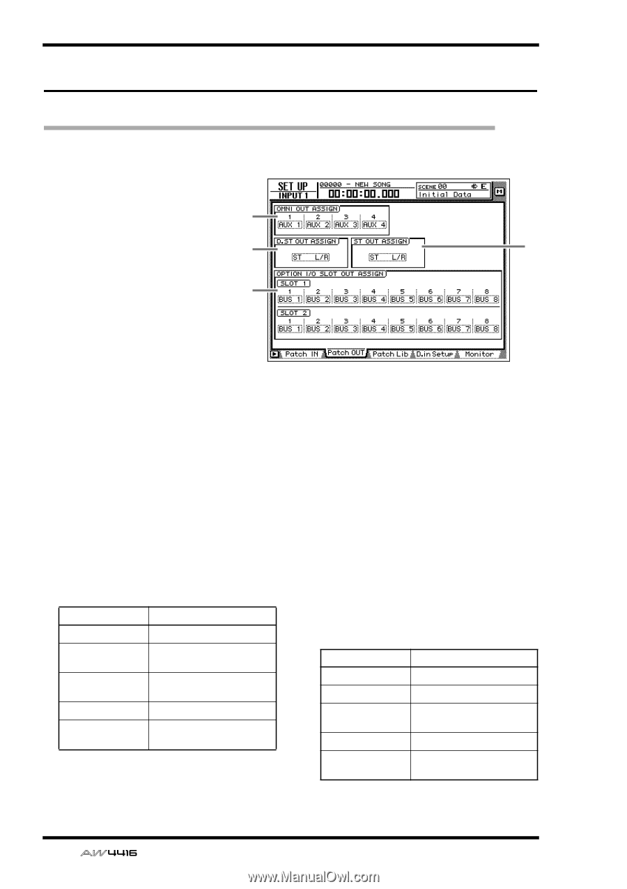
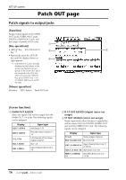
SET UP screen Patch OUT page Patch signals to output jacks [Function] Assign output signals to the OMNI OUT jacks, STEREO OUT jacks, DIGITAL STEREO OUT jack, and the output channels of I/O cards. 1 [Key operations] • [SETUP] key ¡ [F2] (Patch OUT) key (*1) 2 3 • Repeatedly press the [SETUP] key until the display shown at 4 right appears. *1. In the SET UP screen, the tabs displayed at the bottom of the screen are divided into two groups. If the Patch OUT tab is not assigned to the [F2] key when you press the [SETUP] key, press [SHIFT] key + [F1] (CHANGE TAB) key to switch the tabs. [Mouse operation] M button ¡ SETU button ¡ Patch OUT tab [Screen functions] A OMNI OUT ASSIGN Select the signals that will be output from the OMNI OUT 1-4 jacks. The following signals can be assigned. Display AUX 1-AUX 8 RDR 1-RDR16 ST L/ST R BUS 1-BUS8 DIR 1-DIR16 Signal type AUX buses 1-8 Recorder direct outputs 1- 16 L/R channels of the stereo output channel Bus 1-8 Input channel direct out 1- 16 B D.ST OUT ASSIGN (digital stereo out assign) C ST OUT ASSIGN (stereo out assign) These respectively select the pair of signals that will be output from the DIGITAL STEREO OUT jack and the STEREO OUT jack. The following signals can be assigned. Display Signal type ST L/R Stereo output channel BUS 1/2-BUS 7/8 Bus 1/2-7/8 DIR 1/2-DIR15/16 Input channel direct out 1/ 2-15/16 AUX 1/2-AUX 7/8 AUX buses 1/2-7/8 RDR 1/2-RDR15/ Recorder direct outs 1/2- 16 15/16 16 - Reference Guide
-
 1
1 -
2
-
3
-
4
-
5
-
6
-
7
-
8
-
9
-
10
-
11
-
12
-
13
-
14
-
15
-
16
-
17
-
 18
18 -
 19
19 -
 20
20 -
 21
21 -
 22
22 -
 23
23 -
 24
24 -
 25
25 -
 26
26 -
 27
27 -
 28
28 -
29
-
30
-
31
-
32
-
33
-
34
-
35
-
36
-
37
-
38
-
39
-
40
-
41
-
42
-
43
-
44
-
45
-
46
-
47
-
48
-
49
-
50
-
51
-
52
-
53
-
54
-
55
-
56
-
57
-
58
-
59
-
60
-
61
-
62
-
63
-
64
-
65
-
66
-
67
-
68
-
69
-
70
-
71
-
72
-
73
-
74
-
75
-
76
-
77
-
78
-
79
-
80
-
81
-
82
-
83
-
84
-
85
-
86
-
87
-
88
-
89
-
90
-
91
-
92
-
93
-
94
-
95
-
96
-
97
-
98
-
99
-
100
-
101
-
102
-
103
-
104
-
105
-
106
-
107
-
108
-
109
-
110
-
111
-
112
-
113
-
114
-
115
-
116
-
117
-
118
-
119
-
120
-
121
-
122
-
123
-
124
-
125
-
126
-
127
-
128
-
129
-
130
-
131
-
132
-
133
-
134
-
135
-
136
-
137
-
138
-
139
-
140
-
141
-
142
-
143
-
144
-
145
-
146
-
147
-
148
-
149
-
150
-
151
-
152
-
153
-
154
-
155
-
156
-
157
-
158
-
159
-
160
-
161
-
162
-
163
-
164
-
165
-
166
-
167
-
168
-
169
-
170
-
171
-
172
-
173
-
174
-
175
-
176
-
177
-
178
-
179
-
180
-
181
-
182
-
183
-
184
-
185
-
186
-
187
-
188
-
189
-
190
-
191
 |
 |