Yamaha AW4416 Reference Guide - Page 24
Additional functions in the Patch, OUT
 |
View all Yamaha AW4416 manuals
Add to My Manuals
Save this manual to your list of manuals |
Page 24 highlights
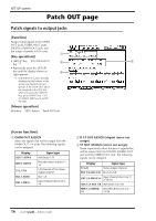
D OPTION I/O SLOT OUT ASSIGN This selects the signals that will be output from I/O cards installed in OPTION I/O slots 1/2. The following signals can be assigned. Display BUS 1-BUS 8 DIR 1-DIR16 AUX 1-AUX 8 RDR 1-RDR16 ST L/ST R Signal type Buses 1-8 Input channel direct out 1- 16 AUX buses 1-8 Recorder direct outputs 1- 16 L/R channels of the stereo output channel Tip! For details on operation in the Patch OUT page, refer to Operation Guide "Chapter 8. Patching." SET UP screen s Additional functions in the Patch OUT page In the Patch OUT page you can press the [SHIFT] key to assign the following function to the [F1] key. F1 • [F1] (CHANGE TAB) key Switch between the two tab displays. 17 - Reference Guide
-
 1
1 -
2
-
3
-
4
-
5
-
6
-
7
-
8
-
9
-
10
-
11
-
12
-
13
-
14
-
15
-
16
-
17
-
18
-
 19
19 -
 20
20 -
 21
21 -
 22
22 -
 23
23 -
 24
24 -
 25
25 -
 26
26 -
 27
27 -
 28
28 -
 29
29 -
30
-
31
-
32
-
33
-
34
-
35
-
36
-
37
-
38
-
39
-
40
-
41
-
42
-
43
-
44
-
45
-
46
-
47
-
48
-
49
-
50
-
51
-
52
-
53
-
54
-
55
-
56
-
57
-
58
-
59
-
60
-
61
-
62
-
63
-
64
-
65
-
66
-
67
-
68
-
69
-
70
-
71
-
72
-
73
-
74
-
75
-
76
-
77
-
78
-
79
-
80
-
81
-
82
-
83
-
84
-
85
-
86
-
87
-
88
-
89
-
90
-
91
-
92
-
93
-
94
-
95
-
96
-
97
-
98
-
99
-
100
-
101
-
102
-
103
-
104
-
105
-
106
-
107
-
108
-
109
-
110
-
111
-
112
-
113
-
114
-
115
-
116
-
117
-
118
-
119
-
120
-
121
-
122
-
123
-
124
-
125
-
126
-
127
-
128
-
129
-
130
-
131
-
132
-
133
-
134
-
135
-
136
-
137
-
138
-
139
-
140
-
141
-
142
-
143
-
144
-
145
-
146
-
147
-
148
-
149
-
150
-
151
-
152
-
153
-
154
-
155
-
156
-
157
-
158
-
159
-
160
-
161
-
162
-
163
-
164
-
165
-
166
-
167
-
168
-
169
-
170
-
171
-
172
-
173
-
174
-
175
-
176
-
177
-
178
-
179
-
180
-
181
-
182
-
183
-
184
-
185
-
186
-
187
-
188
-
189
-
190
-
191
 |
 |

SET UP screen
— Reference Guide
17
D
OPTION I/O SLOT OUT ASSIGN
This selects the signals that will be output from
I/O cards installed in OPTION I/O slots 1/2. The
following signals can be assigned.
Tip!
For details on operation in the Patch OUT
page, refer to Operation Guide “Chapter 8.
Patching.”
■
Additional functions in the Patch
OUT page
In the Patch OUT page you can press the [SHIFT]
key to assign the following function to the [F1] key.
•
[F1] (CHANGE TAB) key
Switch between the two tab displays.
Display
Signal type
BUS 1
–
BUS 8
Buses 1–8
DIR 1
–
DIR16
Input channel direct out 1–
16
AUX 1
–
AUX 8
AUX buses 1–8
RDR 1
–
RDR16
Recorder direct outputs 1–
16
ST L/ST R
L/R channels of the stereo
output channel
F1