Yamaha AW4416 Reference Guide - Page 27
D.in Setup Make word clock/cascade settings
 |
View all Yamaha AW4416 manuals
Add to My Manuals
Save this manual to your list of manuals |
Page 27 highlights
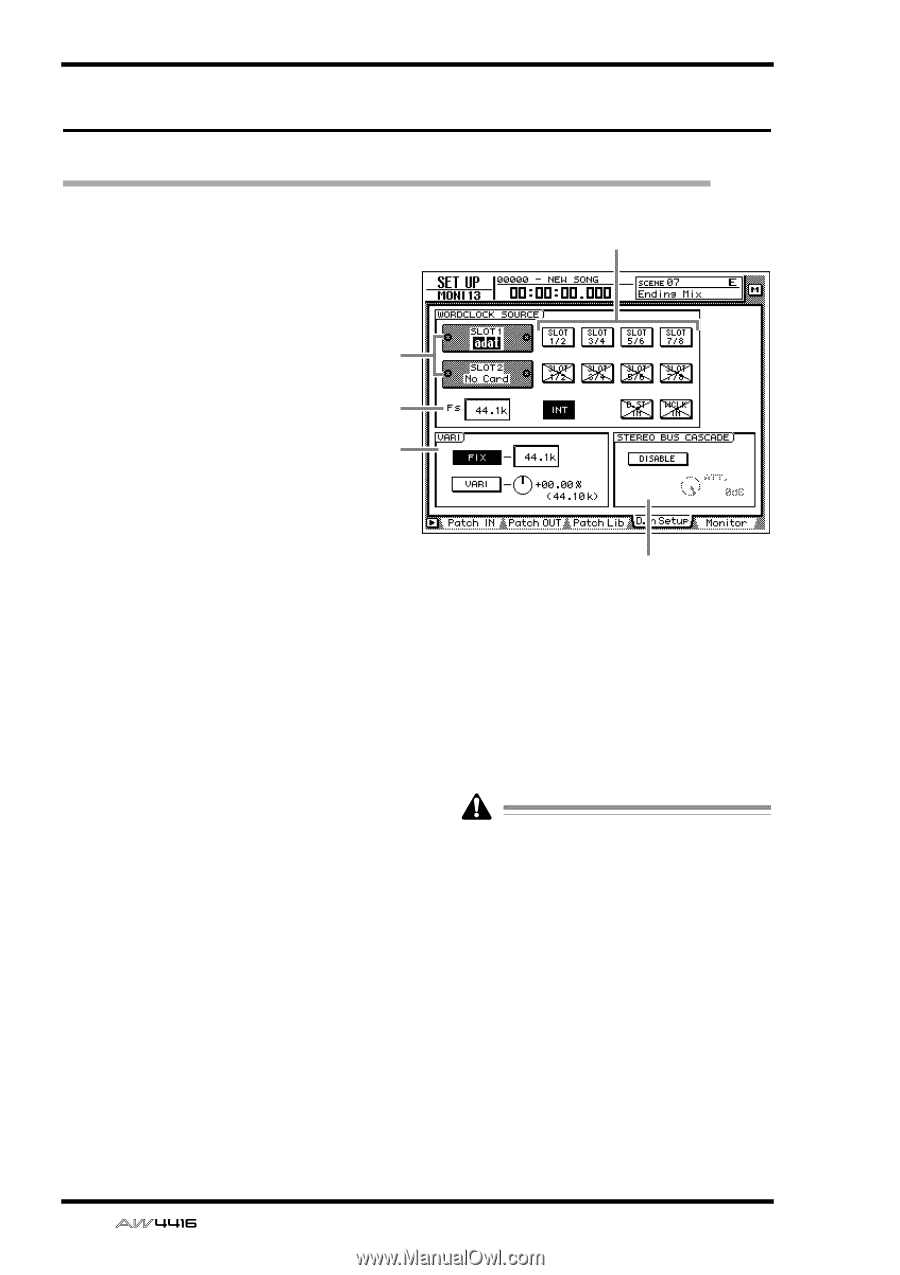
SET UP screen D.in Setup page Make word clock/cascade settings [Function] Select the word clock source to which the AW4416 will synchronize. In this page you can also make settings for stereo bus cascade connections. [Key operation] • [SETUP] key ¡ [F4] (D.in Setup) key (*1) 1 • Repeatedly press the [SETUP] key until the screen shown at the right appears. *1. In the SET UP screen, the tabs dis- 3 played at the bottom of the screen are divided into two groups. If the D.in 4 Setup tab is not assigned to the [F4] key when you press the [SETUP] key, press the [SHIFT] key + [F1] (CHANGE TAB) key to switch the tabs. [Mouse operation] M button ¡ SETU button ¡ D.in Setup tab 2 5 [Screen functions] A Slots 1/2 If an optional I/O card is installed in OPTION I/ O slots 1/2, a graphic will be displayed to show the type of I/O card. Cards in which no card is installed will be displayed as "No Card!" B WORD CLOCK SOURCE From the following choices, select one of the following clock source to which the AW4416 will synchronize. q SLOT 1 1/2-7/8 q SLOT 2 1/2-7/8 The input signal from a digital I/O card installed in OPTION I/O slots 1/2 will be the clock source. One pair of digital I/O card input channels 1/2-7/8 can be selected. q INT The internal clock of the AW4416 will be used as the clock source. q D.ST IN The word clock data included in the input signal of the DIGITAL STEREO IN jack will be the clock source. 20 - Reference Guide q WCLK IN The word clock data included in the input signal of the WORD CLOCK IN jack will be the clock source. • The highlighted button indicates the currently selected word clock source. • Buttons marked with an "X" indicate that no digital audio signal is being input from the corresponding slot/jack. • Buttons marked by a / indicate that a digital audio signal is being input from the corresponding slot/jack, but is not synchronized with the internal clock of the AW4416. • Buttons without an X or / symbol indicate that a digital audio signal is being input from the corresponding slot/jack, and is synchronized with the internal clock of the AW4416.
-
 1
1 -
2
-
3
-
4
-
5
-
6
-
7
-
8
-
9
-
10
-
11
-
12
-
13
-
14
-
15
-
16
-
17
-
18
-
19
-
20
-
21
-
 22
22 -
 23
23 -
 24
24 -
 25
25 -
 26
26 -
 27
27 -
 28
28 -
 29
29 -
 30
30 -
 31
31 -
 32
32 -
33
-
34
-
35
-
36
-
37
-
38
-
39
-
40
-
41
-
42
-
43
-
44
-
45
-
46
-
47
-
48
-
49
-
50
-
51
-
52
-
53
-
54
-
55
-
56
-
57
-
58
-
59
-
60
-
61
-
62
-
63
-
64
-
65
-
66
-
67
-
68
-
69
-
70
-
71
-
72
-
73
-
74
-
75
-
76
-
77
-
78
-
79
-
80
-
81
-
82
-
83
-
84
-
85
-
86
-
87
-
88
-
89
-
90
-
91
-
92
-
93
-
94
-
95
-
96
-
97
-
98
-
99
-
100
-
101
-
102
-
103
-
104
-
105
-
106
-
107
-
108
-
109
-
110
-
111
-
112
-
113
-
114
-
115
-
116
-
117
-
118
-
119
-
120
-
121
-
122
-
123
-
124
-
125
-
126
-
127
-
128
-
129
-
130
-
131
-
132
-
133
-
134
-
135
-
136
-
137
-
138
-
139
-
140
-
141
-
142
-
143
-
144
-
145
-
146
-
147
-
148
-
149
-
150
-
151
-
152
-
153
-
154
-
155
-
156
-
157
-
158
-
159
-
160
-
161
-
162
-
163
-
164
-
165
-
166
-
167
-
168
-
169
-
170
-
171
-
172
-
173
-
174
-
175
-
176
-
177
-
178
-
179
-
180
-
181
-
182
-
183
-
184
-
185
-
186
-
187
-
188
-
189
-
190
-
191
 |
 |