Yamaha AW4416 Reference Guide - Page 52
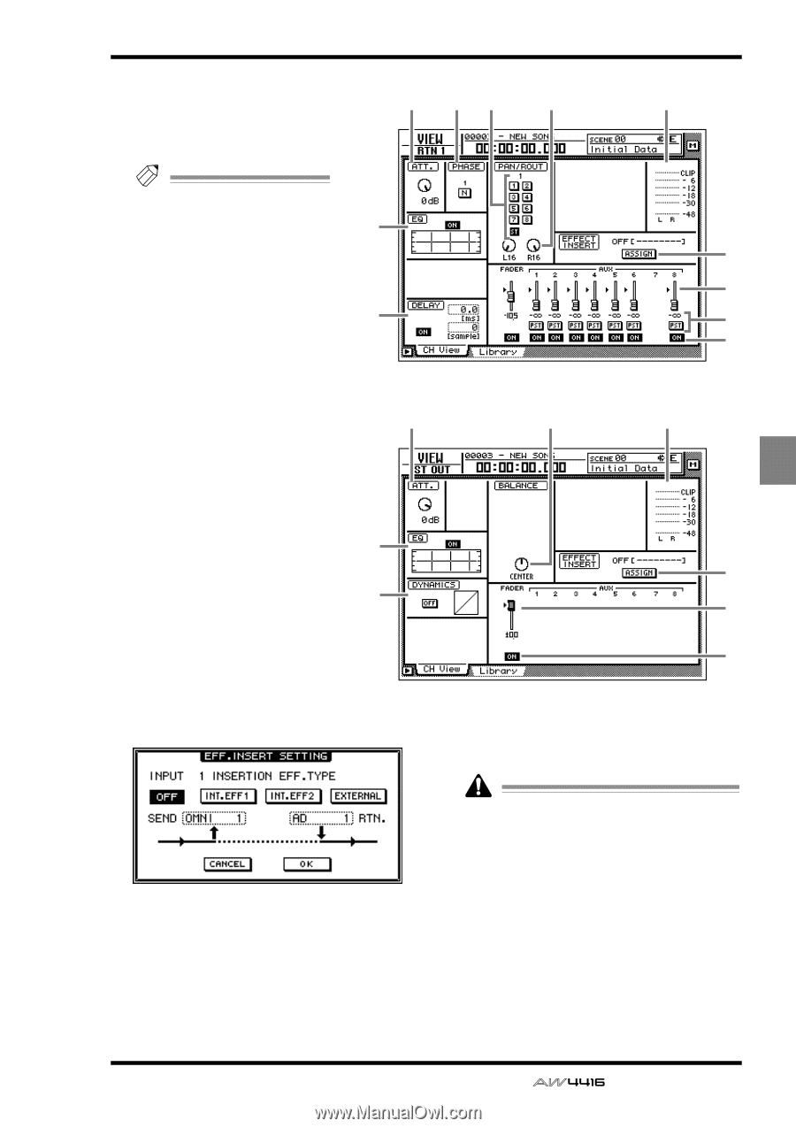
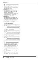
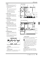
Fader group, Mute group, Input/output meter, ASSIGN button, Return channel, Stereo output channel
 |
View all Yamaha AW4416 manuals
Add to My Manuals
Save this manual to your list of manuals |
Page 52 highlights
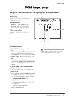
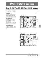
VIEW G PAN Adjust the panning between the L/ R channels of the stereo bus or between odd-numbered ¡ evennumbered buses. Tip! If you move the cursor to the PAN knob and press the [ENTER] key, the knob will move to the center position. H Fader group This area shows the fader group to which the channel belongs. You can also defeat or register groups in this page. I Mute group This area shows the mute group to which the channel belongs. You can also defeat or register groups in this page. J Input/output meter This shows the input level of the input channel, monitor channel, or return channel, and the output level of the stereo output channel. K Pair This shows the pairing status. Pairing can also be set/defeated in this page. L ASSIGN button Use this button to insert an external effect or internal effect into the channel. Move the cursor to this button and press the [ENTER] key to access a screen like the following. q Return channel 1 26 7 VIEW screen J 3 5 q Stereo output channel 1 7 L M N O J 3 L 4 M O q INT.EFF 2 button When this button is on, internal effect 2 will be inserted into the corresponding channel. q OFF button When this button is on, an effect will not be inserted. q INT.EFF 1 button When this button is on, internal effect 1 will be inserted into the corresponding channel. When inserting the internal effect 1/2 into a channel, you must set either EFF1 or EFF2 to "INSERT" in the SETUP screen Patch IN page. If neither of the effects is set to "INSERT," attempting to turn on the INT.EFF1/INT.EFF2 button in this screen will produce an error message of "ERROR INT. EFF NOW SELECTED AUX." q EXTERNAL button When this button is on, you can select the desired input and output jacks for use as the insert send/return jacks for the corresponding channel. 45 - Reference Guide
-
 1
1 -
2
-
3
-
4
-
5
-
6
-
7
-
8
-
9
-
10
-
11
-
12
-
13
-
14
-
15
-
16
-
17
-
18
-
19
-
20
-
21
-
22
-
23
-
24
-
25
-
26
-
27
-
28
-
29
-
30
-
31
-
32
-
33
-
34
-
35
-
36
-
37
-
38
-
39
-
40
-
41
-
42
-
43
-
44
-
45
-
46
-
 47
47 -
 48
48 -
 49
49 -
 50
50 -
 51
51 -
 52
52 -
 53
53 -
 54
54 -
 55
55 -
 56
56 -
 57
57 -
58
-
59
-
60
-
61
-
62
-
63
-
64
-
65
-
66
-
67
-
68
-
69
-
70
-
71
-
72
-
73
-
74
-
75
-
76
-
77
-
78
-
79
-
80
-
81
-
82
-
83
-
84
-
85
-
86
-
87
-
88
-
89
-
90
-
91
-
92
-
93
-
94
-
95
-
96
-
97
-
98
-
99
-
100
-
101
-
102
-
103
-
104
-
105
-
106
-
107
-
108
-
109
-
110
-
111
-
112
-
113
-
114
-
115
-
116
-
117
-
118
-
119
-
120
-
121
-
122
-
123
-
124
-
125
-
126
-
127
-
128
-
129
-
130
-
131
-
132
-
133
-
134
-
135
-
136
-
137
-
138
-
139
-
140
-
141
-
142
-
143
-
144
-
145
-
146
-
147
-
148
-
149
-
150
-
151
-
152
-
153
-
154
-
155
-
156
-
157
-
158
-
159
-
160
-
161
-
162
-
163
-
164
-
165
-
166
-
167
-
168
-
169
-
170
-
171
-
172
-
173
-
174
-
175
-
176
-
177
-
178
-
179
-
180
-
181
-
182
-
183
-
184
-
185
-
186
-
187
-
188
-
189
-
190
-
191
 |
 |