Dell Latitude CPi User Guide - Page 149
Memory Allocations
 |
View all Dell Latitude CPi manuals
Add to My Manuals
Save this manual to your list of manuals |
Page 149 highlights
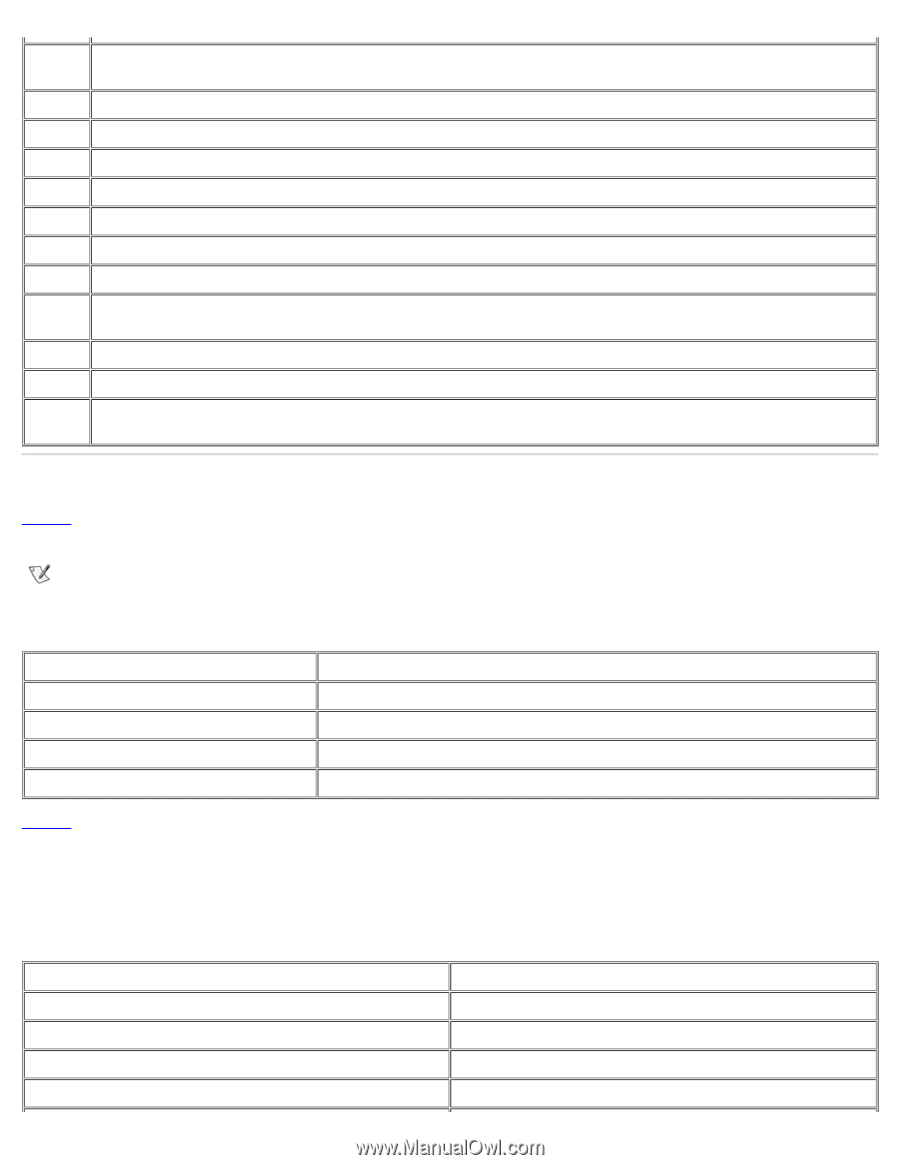
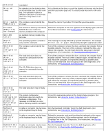
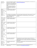
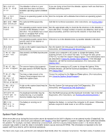
IRQ4 IRQ5 IRQ6 IRQ7 IRQ8 IRQ9 IRQ10 IRQ11 IRQ12 IRQ13 IRQ14 IRQ15 Available for use by a PC Card unless the built-in serial port or infrared port is configured for COM1 (the default) or COM3 Generated by the audio controller Generated by the diskette drive controller to indicate that the diskette drive requires the attention of the microprocessor Available for use by a PC Card or audio controller if the parallel port is disabled Reserved; generated by the system I/O controller's RTC Reserved; generated by the video controller Available for use by a PC Card or audio controller unless the C/Port APR or C/Dock Expansion Station is attached Generated by USB and PC Card controllers; available for use by a PC Card Reserved; generated by the keyboard controller to indicate that the output buffer of the touch pad or external PS/2 mouse is full Reserved; generated by the math coprocessor Reserved; generated by the hard-disk drive to indicate that the drive requires the attention of the microprocessor Reserved; generated by CD-ROM drive in the modular bay to indicate that the drive requires the attention of the microprocessor Memory Allocations Table 4 provides a map of the conventional memory area. When the microprocessor or a program addresses a location within the conventional memory range, it is physically addressing a location in main memory. NOTE: To view memory allocations in Windows 95 and Windows 98, click the Start button, point to Settings, and click Control Panel. Double-click the System icon. Select the Device Manager tab, and then double-click Computer. Table 4. Conventional Memory Map Address Range 0000h-003FFh 00400h-00FFFF 00500h-005FFh 00600h-9FBFFh Use Interrupt vector table BIOS data area MS-DOS® and BASIC work area User memory Table 5 provides a map of the upper memory area. Some of these addresses are dedicated to various system devices, such as the system/video basic input/output system (BIOS). Others are available for use by expansion cards and/or an expanded memory manager (EMM). When the microprocessor or a program addresses a location within the upper memory area, it is physically addressing a location within one of these devices. Table 5. Upper Memory Map Address Range 0009FC00-0009FFFF 000A0000-000BFFFF 000C0000-000CBFFF 000CC000-000CDFFF Use PS/2-mouse data area Video RAM Video BIOS Reserved for PC Card
-
 1
1 -
2
-
3
-
4
-
5
-
6
-
7
-
8
-
9
-
10
-
11
-
12
-
13
-
14
-
15
-
16
-
17
-
18
-
19
-
20
-
21
-
22
-
23
-
24
-
25
-
26
-
27
-
28
-
29
-
30
-
31
-
32
-
33
-
34
-
35
-
36
-
37
-
38
-
39
-
40
-
41
-
42
-
43
-
44
-
45
-
46
-
47
-
48
-
49
-
50
-
51
-
52
-
53
-
54
-
55
-
56
-
57
-
58
-
59
-
60
-
61
-
62
-
63
-
64
-
65
-
66
-
67
-
68
-
69
-
70
-
71
-
72
-
73
-
74
-
75
-
76
-
77
-
78
-
79
-
80
-
81
-
82
-
83
-
84
-
85
-
86
-
87
-
88
-
89
-
90
-
91
-
92
-
93
-
94
-
95
-
96
-
97
-
98
-
99
-
100
-
101
-
102
-
103
-
104
-
105
-
106
-
107
-
108
-
109
-
110
-
111
-
112
-
113
-
114
-
115
-
116
-
117
-
118
-
119
-
120
-
121
-
122
-
123
-
124
-
125
-
126
-
127
-
128
-
129
-
130
-
131
-
132
-
133
-
134
-
135
-
136
-
137
-
138
-
139
-
140
-
141
-
142
-
143
-
 144
144 -
 145
145 -
 146
146 -
 147
147 -
 148
148 -
 149
149 -
 150
150 -
 151
151 -
 152
152 -
 153
153 -
 154
154 -
155
-
156
-
157
-
158
-
159
-
160
-
161
-
162
-
163
-
164
-
165
-
166
-
167
-
168
-
169
-
170
-
171
-
172
-
173
-
174
-
175
-
176
-
177
-
178
-
179
-
180
-
181
-
182
-
183
-
184
-
185
-
186
-
187
-
188
-
189
-
190
-
191
-
192
-
193
-
194
-
195
-
196
-
197
-
198
-
199
-
200
-
201
-
202
-
203
-
204
-
205
-
206
-
207
-
208
 |
 |