Dell Latitude CPi User Guide - Page 90
USB Connector, Serial Connector, Table 1. Parallel Port Pin Assignments, Signal, Definition
 |
View all Dell Latitude CPi manuals
Add to My Manuals
Save this manual to your list of manuals |
Page 90 highlights
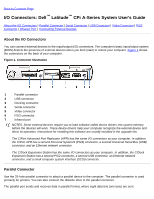
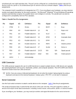
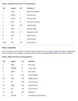
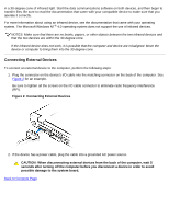
simultaneously over eight separate lines. The port can be configured as a unidirectional (output-only) port for devices such as a printer or as a bidirectional port for devices such as a network adapter. Table 1 lists the pin assignments. The computer's built-in parallel port is designated as LPT1. If you reconfigure your hardware, you may need pin number and signal information for the serial connector. The Microsoft® Windows® 95 and Windows 98 operating systems automatically recognize the parallel device and configure it correctly. The parallel port can also be configured for compatibility with the PS/2 standard. Table 1. Parallel Port Pin Assignments Pin Signal I/O Definition Pin Signal I/O Definition 1 STB# O Strobe 11 BUSY I Busy 2 PD0 I/O Parallel data bit 0 12 PE I Paper end 3 PD1 I/O Parallel data bit 1 13 SLCT I Select 4 PD2 I/O Parallel data bit 2 14 AFD# O Automatic feed 5 PD3 I/O Parallel data bit 3 15 EFF# I Error 6 PD4 I/O Parallel data bit 4 16 INIT# O Initialize printer 7 PD5 I/O Parallel data bit 5 17 SLIN# O Select in 8 PD6 I/O Parallel data bit 6 18-25 N/A N/A Signal ground 9 PD7 I/O Parallel data bit 7 Shell N/A N/A Frame ground 10 ACK# I Acknowledge USB Connector The USB connector supports the use of a USB hub device to attach multiple devices. USB devices are typically low-speed peripherals such as mice, keyboards, printers, and computer speakers. The C/Port APR and C/Dock Expansion Station have two USB connectors. NOTE: If you are using a USB external keyboard, do not enter the System Setup program by using a keyboard command on the external keyboard. Instead, press on the built-in keyboard. Serial Connector Use the 9-pin serial connector to attach a serial device to the computer. Table 2 lists the pin assignments. The serial port passes data in serial format (one bit at a time over one line). This port supports a variety of devices that require serial data transmission, including a serial mouse, serial printer, plotter, or external modem. If you reconfigure your hardware, you may need pin number and signal information for the serial connector.
-
 1
1 -
2
-
3
-
4
-
5
-
6
-
7
-
8
-
9
-
10
-
11
-
12
-
13
-
14
-
15
-
16
-
17
-
18
-
19
-
20
-
21
-
22
-
23
-
24
-
25
-
26
-
27
-
28
-
29
-
30
-
31
-
32
-
33
-
34
-
35
-
36
-
37
-
38
-
39
-
40
-
41
-
42
-
43
-
44
-
45
-
46
-
47
-
48
-
49
-
50
-
51
-
52
-
53
-
54
-
55
-
56
-
57
-
58
-
59
-
60
-
61
-
62
-
63
-
64
-
65
-
66
-
67
-
68
-
69
-
70
-
71
-
72
-
73
-
74
-
75
-
76
-
77
-
78
-
79
-
80
-
81
-
82
-
83
-
84
-
 85
85 -
 86
86 -
 87
87 -
 88
88 -
 89
89 -
 90
90 -
 91
91 -
 92
92 -
 93
93 -
 94
94 -
 95
95 -
96
-
97
-
98
-
99
-
100
-
101
-
102
-
103
-
104
-
105
-
106
-
107
-
108
-
109
-
110
-
111
-
112
-
113
-
114
-
115
-
116
-
117
-
118
-
119
-
120
-
121
-
122
-
123
-
124
-
125
-
126
-
127
-
128
-
129
-
130
-
131
-
132
-
133
-
134
-
135
-
136
-
137
-
138
-
139
-
140
-
141
-
142
-
143
-
144
-
145
-
146
-
147
-
148
-
149
-
150
-
151
-
152
-
153
-
154
-
155
-
156
-
157
-
158
-
159
-
160
-
161
-
162
-
163
-
164
-
165
-
166
-
167
-
168
-
169
-
170
-
171
-
172
-
173
-
174
-
175
-
176
-
177
-
178
-
179
-
180
-
181
-
182
-
183
-
184
-
185
-
186
-
187
-
188
-
189
-
190
-
191
-
192
-
193
-
194
-
195
-
196
-
197
-
198
-
199
-
200
-
201
-
202
-
203
-
204
-
205
-
206
-
207
-
208
 |
 |