Dell Latitude CPi User Guide - Page 150
I/O Memory Map, Start, Settings, Control, Panel, System, Device Manager, Computer
 |
View all Dell Latitude CPi manuals
Add to My Manuals
Save this manual to your list of manuals |
Page 150 highlights
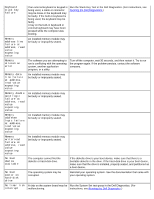
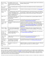
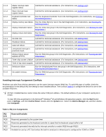
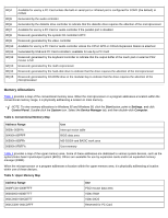
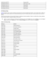
000F0000-000FFFFF 00100000-03FFFFFF FD000000-FDFFFFFF FF200000-FF2FFFFF FFFE0000-FFFFFFFF System BIOS High memory area Video RAM Video RAM BIOS ROM I/O Memory Map Table 6 provides a map of memory addresses reserved by the system for peripheral I/O devices. Use the information in Table 6 to determine if the memory address of an external peripheral (such as a PC Card) conflicts with a memory address reserved by the system. Check the documentation of the external I/O device to determine its memory address. If there is a conflict with a memory address reserved by the system, change the address of the device. NOTE: To view I/O addresses in Windows 95 and Windows 98, click the Start button, point to Settings, and click Control Panel. Double-click the System icon. Click the Device Manager tab, and then double-click Computer. Table 6. I/O Memory Map Address 0000-001F 0020-003F 0040-005F 0060-006F 0070-007F 0080-009F 00A0-00BF 00C0-00DF 00F0-00FF 0170-0177 01F0-01F7 0210-0217 0220-022F 0270-0277 0376-0376 0378-037F 0388-038B 038B-03BB 03C0-03DF 03E0-03E1 03E8-03EF Device DMA controller #1 Interrupt controller #1 System timers Keyboard controller RTC and NMI enable DMA page registers Interrupt controller #2 DMA controller #2 Math coprocessor CD-ROM controller Hard-disk drive controller Audio controller Audio controller Fast IR IDE controller LPT1 Audio controller VGA VGA PC Card controller Fast IR
-
 1
1 -
2
-
3
-
4
-
5
-
6
-
7
-
8
-
9
-
10
-
11
-
12
-
13
-
14
-
15
-
16
-
17
-
18
-
19
-
20
-
21
-
22
-
23
-
24
-
25
-
26
-
27
-
28
-
29
-
30
-
31
-
32
-
33
-
34
-
35
-
36
-
37
-
38
-
39
-
40
-
41
-
42
-
43
-
44
-
45
-
46
-
47
-
48
-
49
-
50
-
51
-
52
-
53
-
54
-
55
-
56
-
57
-
58
-
59
-
60
-
61
-
62
-
63
-
64
-
65
-
66
-
67
-
68
-
69
-
70
-
71
-
72
-
73
-
74
-
75
-
76
-
77
-
78
-
79
-
80
-
81
-
82
-
83
-
84
-
85
-
86
-
87
-
88
-
89
-
90
-
91
-
92
-
93
-
94
-
95
-
96
-
97
-
98
-
99
-
100
-
101
-
102
-
103
-
104
-
105
-
106
-
107
-
108
-
109
-
110
-
111
-
112
-
113
-
114
-
115
-
116
-
117
-
118
-
119
-
120
-
121
-
122
-
123
-
124
-
125
-
126
-
127
-
128
-
129
-
130
-
131
-
132
-
133
-
134
-
135
-
136
-
137
-
138
-
139
-
140
-
141
-
142
-
143
-
144
-
 145
145 -
 146
146 -
 147
147 -
 148
148 -
 149
149 -
 150
150 -
 151
151 -
 152
152 -
 153
153 -
 154
154 -
 155
155 -
156
-
157
-
158
-
159
-
160
-
161
-
162
-
163
-
164
-
165
-
166
-
167
-
168
-
169
-
170
-
171
-
172
-
173
-
174
-
175
-
176
-
177
-
178
-
179
-
180
-
181
-
182
-
183
-
184
-
185
-
186
-
187
-
188
-
189
-
190
-
191
-
192
-
193
-
194
-
195
-
196
-
197
-
198
-
199
-
200
-
201
-
202
-
203
-
204
-
205
-
206
-
207
-
208
 |
 |
