HP Color LaserJet CM2320 Service Manual - Page 102
Fuser protective function, Fuser failure detection, DC controller, Fuser heater safety circuit
 |
View all HP Color LaserJet CM2320 manuals
Add to My Manuals
Save this manual to your list of manuals |
Page 102 highlights
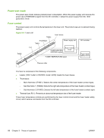
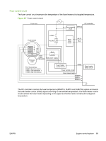
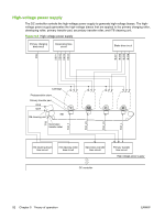
Fuser protective function The protective function detects an abnormal temperature rise of the fuser and interrupts power supply to the fuser heater. The following protective components prevent an abnormal temperature rise of the fuser heater. ● DC controller: The DC controller monitors the detected temperature of the thermistors. It deactivates the fuser heater control signal and releases the relay to interrupt the power supply to the fuser heater under the following conditions. ◦ Main thermistor: 253°C (487.4°F) or higher ◦ Sub thermistor 1: 273°C (523.4°F) or higher ◦ Sub thermistor 2: 273°C (523.4°F) or higher ● Fuser heater safety circuit: The fuser heater safety circuit monitors the detected temperature of the thermistors. It releases the relay to interrupt the power supply to the fuser heater under the following conditions. ◦ Main thermistor: 320°C (608°F) or higher ◦ Sub thermistor 1: 295°C (563°F) or higher ◦ Sub thermistor 2: 295°C (563°F) or higher ● Thermal fuse: The thermal fuse blows to interrupt power supply to the fuser heater if the thermal fuse temperature reaches 228°C (442°F) or higher. Fuser failure detection The DC controller determines a fuser unit failure, deactivates the fuser heater control signal, releases the relay to interrupt power supply to the fuser heater, and then notifies the formatter of a failure state when it encounters the following conditions. ● Start-up failure conditions ◦ The main thermistor temperature does not reach 50°C (122°F) within a specified period of heater startup during the wait period. ◦ The main thermistor temperature does not reach the targeted temperature within a specified period after the temperature once reaches 50°C (122°F) from the heater startup during the wait period. ◦ The main thermistor temperature does not reach the targeted temperature within a specified period under the heater temperature control during the initial rotation period. ● Abnormal low temperature conditions ◦ The main thermistor temperature remains at 100°C (212°F) or lower for a specified period under the heater temperature control during the print period. 90 Chapter 5 Theory of operation ENWW
-
 1
1 -
2
-
3
-
4
-
5
-
6
-
7
-
8
-
9
-
10
-
11
-
12
-
13
-
14
-
15
-
16
-
17
-
18
-
19
-
20
-
21
-
22
-
23
-
24
-
25
-
26
-
27
-
28
-
29
-
30
-
31
-
32
-
33
-
34
-
35
-
36
-
37
-
38
-
39
-
40
-
41
-
42
-
43
-
44
-
45
-
46
-
47
-
48
-
49
-
50
-
51
-
52
-
53
-
54
-
55
-
56
-
57
-
58
-
59
-
60
-
61
-
62
-
63
-
64
-
65
-
66
-
67
-
68
-
69
-
70
-
71
-
72
-
73
-
74
-
75
-
76
-
77
-
78
-
79
-
80
-
81
-
82
-
83
-
84
-
85
-
86
-
87
-
88
-
89
-
90
-
91
-
92
-
93
-
94
-
95
-
96
-
 97
97 -
 98
98 -
 99
99 -
 100
100 -
 101
101 -
 102
102 -
 103
103 -
 104
104 -
 105
105 -
 106
106 -
 107
107 -
108
-
109
-
110
-
111
-
112
-
113
-
114
-
115
-
116
-
117
-
118
-
119
-
120
-
121
-
122
-
123
-
124
-
125
-
126
-
127
-
128
-
129
-
130
-
131
-
132
-
133
-
134
-
135
-
136
-
137
-
138
-
139
-
140
-
141
-
142
-
143
-
144
-
145
-
146
-
147
-
148
-
149
-
150
-
151
-
152
-
153
-
154
-
155
-
156
-
157
-
158
-
159
-
160
-
161
-
162
-
163
-
164
-
165
-
166
-
167
-
168
-
169
-
170
-
171
-
172
-
173
-
174
-
175
-
176
-
177
-
178
-
179
-
180
-
181
-
182
-
183
-
184
-
185
-
186
-
187
-
188
-
189
-
190
-
191
-
192
-
193
-
194
-
195
-
196
-
197
-
198
-
199
-
200
-
201
-
202
-
203
-
204
-
205
-
206
-
207
-
208
-
209
-
210
-
211
-
212
-
213
-
214
-
215
-
216
-
217
-
218
-
219
-
220
-
221
-
222
-
223
-
224
-
225
-
226
-
227
-
228
-
229
-
230
-
231
-
232
-
233
-
234
-
235
-
236
-
237
-
238
-
239
-
240
-
241
-
242
-
243
-
244
-
245
-
246
-
247
-
248
-
249
-
250
-
251
-
252
-
253
-
254
-
255
-
256
-
257
-
258
-
259
-
260
-
261
-
262
-
263
-
264
-
265
-
266
-
267
-
268
-
269
-
270
-
271
-
272
-
273
-
274
-
275
-
276
-
277
-
278
-
279
-
280
-
281
-
282
-
283
-
284
-
285
-
286
-
287
-
288
-
289
-
290
-
291
-
292
-
293
-
294
-
295
-
296
-
297
-
298
-
299
-
300
-
301
-
302
-
303
-
304
-
305
-
306
-
307
-
308
-
309
-
310
-
311
-
312
-
313
-
314
-
315
-
316
-
317
-
318
-
319
-
320
-
321
-
322
-
323
-
324
-
325
-
326
-
327
-
328
-
329
-
330
-
331
-
332
-
333
-
334
-
335
-
336
-
337
-
338
-
339
-
340
-
341
-
342
-
343
-
344
-
345
-
346
-
347
-
348
-
349
-
350
-
351
-
352
-
353
-
354
-
355
-
356
-
357
-
358
-
359
-
360
-
361
-
362
-
363
-
364
-
365
-
366
-
367
-
368
-
369
-
370
-
371
-
372
-
373
-
374
-
375
-
376
-
377
-
378
-
379
-
380
-
381
-
382
-
383
-
384
-
385
-
386
-
387
-
388
-
389
-
390
-
391
-
392
-
393
-
394
-
395
-
396
-
397
-
398
-
399
-
400
-
401
-
402
-
403
-
404
-
405
-
406
-
407
-
408
-
409
-
410
 |
 |
