HP Color LaserJet CM2320 Service Manual - Page 173
DC controller PCA, Special considerations, Remove the DC controller PCA
 |
View all HP Color LaserJet CM2320 manuals
Add to My Manuals
Save this manual to your list of manuals |
Page 173 highlights
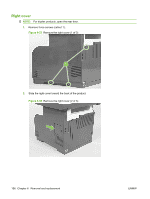
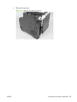
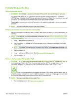
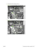
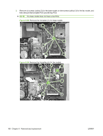
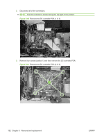
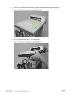
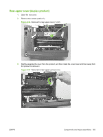
DC controller PCA Special considerations WARNING! Do not install a replacement formatter PCA and a replacement DC controller PCA at the same time. The formatter PCA and the DC controller PCA store important product configuration information (NVRAM data) that is lost if both PCAs are replaced at the same time. When the product power is turned on, the formatter restores the NVRAM data to a replacement DC controller. Replacing both the DC controller and the formatter at the same time will result in severe print-quality problems. Replacing the DC controller PCA before the formatter PCA Use the following procedure if you need to install a replacement DC controller and a replacement formatter PCA. NOTE: If you are only installing a replacement DC controller PCA, go to Remove the DC controller PCA on page 161. 1. Install a replacement DC controller PCA. 2. Turn the product on, and wait for the print-cartridge volume indicators to appear on the controlpanel display. NOTE: This allows important product information to be written to the replacement DC controller PCA. 3. Turn the product off. 4. Install a replacement formatter PCA. See Formatter PCA and fax PCA on page 158. 5. Turn the product on. Remove the DC controller PCA CAUTION: Do not bend or fold the flat flexible cables (FFCs) during removal or installation. Also, do not straighten pre-folds in the FFCs. You must make sure that all FFCs are fully seated in their connectors. Failure to fully seat an FFC into a connector can cause a short circuit in a PCA. Some parts are sensitive to electrostatic discharge (ESD). Always perform service work at an ESD-protected workstation or mat. If an ESD workstation or mat is not available, ground yourself by touching the sheet-metal chassis before touching an ESD-sensitive part. 1. Remove the following components: ● Right cover. See Right cover on page 156. ● Scanner assembly. See Scanner assembly on page 163. ● Upper cover. See Upper-cover assembly on page 181. ENWW Components and major assemblies 161
-
 1
1 -
2
-
3
-
4
-
5
-
6
-
7
-
8
-
9
-
10
-
11
-
12
-
13
-
14
-
15
-
16
-
17
-
18
-
19
-
20
-
21
-
22
-
23
-
24
-
25
-
26
-
27
-
28
-
29
-
30
-
31
-
32
-
33
-
34
-
35
-
36
-
37
-
38
-
39
-
40
-
41
-
42
-
43
-
44
-
45
-
46
-
47
-
48
-
49
-
50
-
51
-
52
-
53
-
54
-
55
-
56
-
57
-
58
-
59
-
60
-
61
-
62
-
63
-
64
-
65
-
66
-
67
-
68
-
69
-
70
-
71
-
72
-
73
-
74
-
75
-
76
-
77
-
78
-
79
-
80
-
81
-
82
-
83
-
84
-
85
-
86
-
87
-
88
-
89
-
90
-
91
-
92
-
93
-
94
-
95
-
96
-
97
-
98
-
99
-
100
-
101
-
102
-
103
-
104
-
105
-
106
-
107
-
108
-
109
-
110
-
111
-
112
-
113
-
114
-
115
-
116
-
117
-
118
-
119
-
120
-
121
-
122
-
123
-
124
-
125
-
126
-
127
-
128
-
129
-
130
-
131
-
132
-
133
-
134
-
135
-
136
-
137
-
138
-
139
-
140
-
141
-
142
-
143
-
144
-
145
-
146
-
147
-
148
-
149
-
150
-
151
-
152
-
153
-
154
-
155
-
156
-
157
-
158
-
159
-
160
-
161
-
162
-
163
-
164
-
165
-
166
-
167
-
 168
168 -
 169
169 -
 170
170 -
 171
171 -
 172
172 -
 173
173 -
 174
174 -
 175
175 -
 176
176 -
 177
177 -
 178
178 -
179
-
180
-
181
-
182
-
183
-
184
-
185
-
186
-
187
-
188
-
189
-
190
-
191
-
192
-
193
-
194
-
195
-
196
-
197
-
198
-
199
-
200
-
201
-
202
-
203
-
204
-
205
-
206
-
207
-
208
-
209
-
210
-
211
-
212
-
213
-
214
-
215
-
216
-
217
-
218
-
219
-
220
-
221
-
222
-
223
-
224
-
225
-
226
-
227
-
228
-
229
-
230
-
231
-
232
-
233
-
234
-
235
-
236
-
237
-
238
-
239
-
240
-
241
-
242
-
243
-
244
-
245
-
246
-
247
-
248
-
249
-
250
-
251
-
252
-
253
-
254
-
255
-
256
-
257
-
258
-
259
-
260
-
261
-
262
-
263
-
264
-
265
-
266
-
267
-
268
-
269
-
270
-
271
-
272
-
273
-
274
-
275
-
276
-
277
-
278
-
279
-
280
-
281
-
282
-
283
-
284
-
285
-
286
-
287
-
288
-
289
-
290
-
291
-
292
-
293
-
294
-
295
-
296
-
297
-
298
-
299
-
300
-
301
-
302
-
303
-
304
-
305
-
306
-
307
-
308
-
309
-
310
-
311
-
312
-
313
-
314
-
315
-
316
-
317
-
318
-
319
-
320
-
321
-
322
-
323
-
324
-
325
-
326
-
327
-
328
-
329
-
330
-
331
-
332
-
333
-
334
-
335
-
336
-
337
-
338
-
339
-
340
-
341
-
342
-
343
-
344
-
345
-
346
-
347
-
348
-
349
-
350
-
351
-
352
-
353
-
354
-
355
-
356
-
357
-
358
-
359
-
360
-
361
-
362
-
363
-
364
-
365
-
366
-
367
-
368
-
369
-
370
-
371
-
372
-
373
-
374
-
375
-
376
-
377
-
378
-
379
-
380
-
381
-
382
-
383
-
384
-
385
-
386
-
387
-
388
-
389
-
390
-
391
-
392
-
393
-
394
-
395
-
396
-
397
-
398
-
399
-
400
-
401
-
402
-
403
-
404
-
405
-
406
-
407
-
408
-
409
-
410
 |
 |