HP Color LaserJet CM2320 Service Manual - Page 130
Removal and replacement strategy, General cautions during removal and replacement
 |
View all HP Color LaserJet CM2320 manuals
Add to My Manuals
Save this manual to your list of manuals |
Page 130 highlights
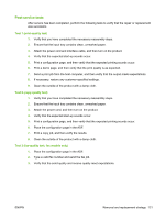
Removal and replacement strategy This chapter discusses the removal and replacement of field replaceable units (FRUs) only. Replacing FRUs is generally the reverse of removal. Occasionally, notes and tips are included to provide directions for difficult or critical replacement procedures. HP does not support repairing individual subassemblies or problem solving at the component level. Note the length, diameter, color, type, and location of each screw. Be sure to return each screw to its original location during reassembly. Incorrectly routed or loose wire harnesses can interfere with other internal components and can become damaged or broken. Frayed or pinched harness wires can be difficult to locate. When replacing wire harnesses, always use the provided wire loops, lance points, or wire-harness guides. General cautions during removal and replacement WARNING! Turn the product off, wait 5 seconds, and then remove the power cord before attempting to service the product. If this warning is not followed, severe injury can result, as well as damage to the product. The power must be on for certain functional checks during problem solving. However, the power cord should be disconnected during parts removal. Never operate or service the product with the protective cover removed from the laser/scanner assembly. The reflected beam, although invisible, can damage your eyes. The sheet-metal parts can have sharp edges. Be careful when handling sheet-metal parts. CAUTION: Do not bend or fold the flat flexible cables (FFCs) during removal or installation. Also, do not straighten pre-folds in the FFCs. You must make sure that all FFCs are fully seated in their connectors. Failure to fully seat an FFC into a connector can cause a short circuit in a PCA. Avoid pulling directly on wires to disconnect wire-harness connectors. Pull on the plastic body of a connector when ever possible to avoid damaging the connector wires. NOTE: To install a self-tapping screw, first turn it counterclockwise to align it with the existing thread pattern, and then carefully turn it clockwise to tighten. Do not overtighten. If a self-tapping screw-hole becomes stripped, repair the screw-hole or replace the affected assembly. Electrostatic discharge CAUTION: Some parts are sensitive to electrostatic discharge (ESD). Look for the ESD reminder when removing product parts. Always perform service work at an ESD-protected workstation or mat. If an ESD workstation or mat is not available, ground yourself by touching the sheet-metal chassis before touching an ESD-sensitive part. Protect the ESD-sensitive parts by placing them in ESD pouches when they are out of the product. 118 Chapter 6 Removal and replacement ENWW
-
 1
1 -
2
-
3
-
4
-
5
-
6
-
7
-
8
-
9
-
10
-
11
-
12
-
13
-
14
-
15
-
16
-
17
-
18
-
19
-
20
-
21
-
22
-
23
-
24
-
25
-
26
-
27
-
28
-
29
-
30
-
31
-
32
-
33
-
34
-
35
-
36
-
37
-
38
-
39
-
40
-
41
-
42
-
43
-
44
-
45
-
46
-
47
-
48
-
49
-
50
-
51
-
52
-
53
-
54
-
55
-
56
-
57
-
58
-
59
-
60
-
61
-
62
-
63
-
64
-
65
-
66
-
67
-
68
-
69
-
70
-
71
-
72
-
73
-
74
-
75
-
76
-
77
-
78
-
79
-
80
-
81
-
82
-
83
-
84
-
85
-
86
-
87
-
88
-
89
-
90
-
91
-
92
-
93
-
94
-
95
-
96
-
97
-
98
-
99
-
100
-
101
-
102
-
103
-
104
-
105
-
106
-
107
-
108
-
109
-
110
-
111
-
112
-
113
-
114
-
115
-
116
-
117
-
118
-
119
-
120
-
121
-
122
-
123
-
124
-
 125
125 -
 126
126 -
 127
127 -
 128
128 -
 129
129 -
 130
130 -
 131
131 -
 132
132 -
 133
133 -
 134
134 -
 135
135 -
136
-
137
-
138
-
139
-
140
-
141
-
142
-
143
-
144
-
145
-
146
-
147
-
148
-
149
-
150
-
151
-
152
-
153
-
154
-
155
-
156
-
157
-
158
-
159
-
160
-
161
-
162
-
163
-
164
-
165
-
166
-
167
-
168
-
169
-
170
-
171
-
172
-
173
-
174
-
175
-
176
-
177
-
178
-
179
-
180
-
181
-
182
-
183
-
184
-
185
-
186
-
187
-
188
-
189
-
190
-
191
-
192
-
193
-
194
-
195
-
196
-
197
-
198
-
199
-
200
-
201
-
202
-
203
-
204
-
205
-
206
-
207
-
208
-
209
-
210
-
211
-
212
-
213
-
214
-
215
-
216
-
217
-
218
-
219
-
220
-
221
-
222
-
223
-
224
-
225
-
226
-
227
-
228
-
229
-
230
-
231
-
232
-
233
-
234
-
235
-
236
-
237
-
238
-
239
-
240
-
241
-
242
-
243
-
244
-
245
-
246
-
247
-
248
-
249
-
250
-
251
-
252
-
253
-
254
-
255
-
256
-
257
-
258
-
259
-
260
-
261
-
262
-
263
-
264
-
265
-
266
-
267
-
268
-
269
-
270
-
271
-
272
-
273
-
274
-
275
-
276
-
277
-
278
-
279
-
280
-
281
-
282
-
283
-
284
-
285
-
286
-
287
-
288
-
289
-
290
-
291
-
292
-
293
-
294
-
295
-
296
-
297
-
298
-
299
-
300
-
301
-
302
-
303
-
304
-
305
-
306
-
307
-
308
-
309
-
310
-
311
-
312
-
313
-
314
-
315
-
316
-
317
-
318
-
319
-
320
-
321
-
322
-
323
-
324
-
325
-
326
-
327
-
328
-
329
-
330
-
331
-
332
-
333
-
334
-
335
-
336
-
337
-
338
-
339
-
340
-
341
-
342
-
343
-
344
-
345
-
346
-
347
-
348
-
349
-
350
-
351
-
352
-
353
-
354
-
355
-
356
-
357
-
358
-
359
-
360
-
361
-
362
-
363
-
364
-
365
-
366
-
367
-
368
-
369
-
370
-
371
-
372
-
373
-
374
-
375
-
376
-
377
-
378
-
379
-
380
-
381
-
382
-
383
-
384
-
385
-
386
-
387
-
388
-
389
-
390
-
391
-
392
-
393
-
394
-
395
-
396
-
397
-
398
-
399
-
400
-
401
-
402
-
403
-
404
-
405
-
406
-
407
-
408
-
409
-
410
 |
 |
