Kyocera FS-9100DN FS-9100/9500 Operation Guide Rev-1.3 - Page 95
Appendix C Host Computer Interface, 1. Parallel Interface, 1.1 Parallel Interface Communication Modes
 |
UPC - 632983001066
View all Kyocera FS-9100DN manuals
Add to My Manuals
Save this manual to your list of manuals |
Page 95 highlights
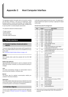
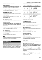
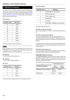
Appendix C Host Computer Interface This appendix explains the signals used in the printer's parallel and RS-232C interfaces. It also lists pin assignments, signal functions, timings, connector specifications, and voltage levels. The RS-232C protocols are also covered. Finally, it explains how to use the printer in a multi-computer environment. This appendix explains the following topics: • Parallel Interface • Serial Interface • RS-232C Protocol • RS-232C Cable Connection 1. Parallel Interface 1.1 Parallel Interface Communication Modes The printer features fast data transmission with the parallel interface. The parallel interface mode can be activated from the operator panel. See Changing Parallel Interface Modes on page 3-18. NOTE Use a parallel printer cable that complies with the IEEE1284 standard. Nibble (high) [default] High speed data communication is used in compliance with the IEEE1284 standard. Ordinarily, you should leave this setting unchanged. Auto The printer automatically changes its communication mode to the one the host computer is currently using. Normal The printer uses the standard communication method prescribed for Centronics interfaces. High-speed This mode enables faster data transmission between the printer and the host computer. (Select this mode if printing problems occur when the printer is connected to a workstation.) 1.2 Interface Signals The pins of the parallel interface connector carry the signals listed in the table in Parallel Connector Pin Assignment. Asterisks C-1 in the table indicate signals that are low active. The table also indicates whether each signal is incoming or outgoing with respect to the printer. Parallel Connector Pin Assignment Pin In/out Description 1 In Strobe* [nStrobe] 2 In/Out Data 0 [Data 1] 3 In/Out Data 1 [Data 2] 4 In/Out Data 2 [Data 3] 5 In/Out Data 3 [Data 4] 6 In/Out Data 4 [Data 5] 7 In/Out Data 5 [Data 6] 8 In/Out Data 6 [Data 7] 9 In/Out Data 7 [Data 8] 10 Out Acknowledge* [nAck] 11 Out Busy [Busy] 12 Out Paper Empty [PError], returns paper empty status if FRPO O2=2 13 Out Online (Select) [nSelect], returns off-line status if FRPO O2=2 14 In Auto-feed [nAutoFd] 15 - Not connected 16 - 0 V DC 17 - Chassis GND 18 - +5 V DC 19 - Ground 20 - Ground 21 - Ground 22 - Ground 23 - Ground 24 - Ground 25 - Ground 26 - Ground 27 - Ground 28 - Ground 29 - Ground 30 - Ground 31 In Ignored [nInit] 32 Out Error*, returns error status if FRPO O2=2 [nFault] 33 - Not connected 34 - Not connected 35 Out Power Ready 36 In Ignored [nSelectIn] [ ]: Signal names in the Auto mode and Nibble (high) mode (IEEE1284). In the Auto mode and Nibble (high) mode, these signals are bidirectional.
-
 1
1 -
2
-
3
-
4
-
5
-
6
-
7
-
8
-
9
-
10
-
11
-
12
-
13
-
14
-
15
-
16
-
17
-
18
-
19
-
20
-
21
-
22
-
23
-
24
-
25
-
26
-
27
-
28
-
29
-
30
-
31
-
32
-
33
-
34
-
35
-
36
-
37
-
38
-
39
-
40
-
41
-
42
-
43
-
44
-
45
-
46
-
47
-
48
-
49
-
50
-
51
-
52
-
53
-
54
-
55
-
56
-
57
-
58
-
59
-
60
-
61
-
62
-
63
-
64
-
65
-
66
-
67
-
68
-
69
-
70
-
71
-
72
-
73
-
74
-
75
-
76
-
77
-
78
-
79
-
80
-
81
-
82
-
83
-
84
-
85
-
86
-
87
-
88
-
89
-
 90
90 -
 91
91 -
 92
92 -
 93
93 -
 94
94 -
 95
95 -
 96
96 -
 97
97 -
 98
98 -
 99
99 -
 100
100 -
101
-
102
-
103
-
104
-
105
-
106
-
107
-
108
-
109
-
110
-
111
-
112
-
113
-
114
-
115
-
116
-
117
-
118
-
119
-
120
-
121
-
122
-
123
-
124
-
125
-
126
-
127
-
128
-
129
-
130
-
131
-
132
-
133
-
134
-
135
-
136
-
137
-
138
-
139
-
140
-
141
-
142
-
143
 |
 |