Kyocera FS-9100DN FS-9100/9500 Operation Guide Rev-1.3 - Page 96
Serial Interface, 2.1 Interface Signals
 |
UPC - 632983001066
View all Kyocera FS-9100DN manuals
Add to My Manuals
Save this manual to your list of manuals |
Page 96 highlights
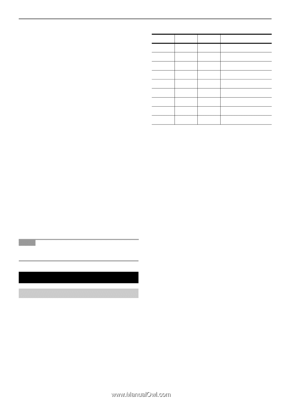
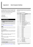
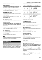
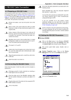
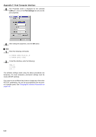
Detailed descriptions of the signals follow. Strobe* [nStrobe] (Pin 1) A negative-going Strobe* pulse causes the printer to read and latch the data on the Data 0 [1] to Data 7 [8] signal lines. Data 0 [1] to Data 7 [8] (Pins 2 to 9) These eight signals form the data byte sent from the host computer to the printer. Data 7 [8] is the most significant bit. Acknowledge* [nAck] (Pin 10) This negative-going pulse acknowledges the previous character received by the printer. Busy [Busy] (Pin 11) This signal is high when the printer is busy and low when it is able to accept more data. Paper Empty [PError] (Pin 12) This signal goes high when the printer has received a print job and run out of paper. Online [Select] (Pin 13) This signal is high when the printer is online and low when the printer is offline. It goes low when the GO key is pressed to set the printer offline. +5 V DC (Pin 18) This line is connected to the printer's +5 V DC line (+5 V ±0.5 V, maximum 400 mA [Serial and Parallel total], fused). Error* [nFault] (Pin 32) When the high-speed parallel line control is on (FRPO O2=2), this line returns error status. Power Ready (Pin 35) This signal is high when the printer is turned on. NOTE The Paper Empty, Online, and Error signals are not used unless enabled by the FRPO command (O2 parameter). 2. Serial Interface 2.1 Interface Signals The pins of the printer's RS-232C interface connector carry the signals listed in the table below. The table also indicates whether each signal is incoming or outgoing with respect to the printer. Appendix C Host Computer Interface RS-232C Signal Pin Assignment Pin In/out Signal Description 1 - FG Frame ground 2 Out TXD Transmit Data 3 In RXD Receive Data 4 Out RTS Request To Send 5 In CTS Clear To Send 6 In DSR Data Set Ready 7 - SG Signal Ground 11 - +5 V DC Reserved 20 Out DTR Data Terminal Ready Brief descriptions of the signals follow. FG - Frame Ground - (Pin 1) This pin is connected directly to the printer frame. TXD - Transmit Data - (Pin 2) This output carries asynchronous data sent by the printer to the computer. It is used mainly in handshaking protocols. RXD - Receive Data - (Pin 3) This input carries serial asynchronous data sent by the computer to the printer. RTS - Request To Send - (Pin 4) This output is always held high (above 3 volts). CTS - Clear To Send - (Pin 5) DSR - Data Set Ready - (Pin 6) Unused. SG - Signal Ground - (Pin 7) All signals can transmit between the printer and the host computer to send each signal with a signal ground. +5 V DC - (Pin 11) This line is connected to the printer's +5 V DC line (+5 V ±0.5 V, maximum 250 mA, fused). DTR - Data Terminal Ready - (Pin 20) This output is used as a buffer nearly-full handshake line. It is held high (above 3 volts) when the buffer can accept more data. Q RS-232C Interface Voltage Levels The voltage levels of the interface signals conform to EIA RS232C specifications. SPACE is from 3 volts to 15 volts. MARK is from -3 volts to -15 volts. Voltages between -3 volts and 3 volts are undefined. Q SERIAL Connector The connector marked IOIOI (RS-232C) on the rear panel is a DB-25S connector. Use a DB-25P connector (or equivalent) for the connector on the cable. C-2
-
 1
1 -
2
-
3
-
4
-
5
-
6
-
7
-
8
-
9
-
10
-
11
-
12
-
13
-
14
-
15
-
16
-
17
-
18
-
19
-
20
-
21
-
22
-
23
-
24
-
25
-
26
-
27
-
28
-
29
-
30
-
31
-
32
-
33
-
34
-
35
-
36
-
37
-
38
-
39
-
40
-
41
-
42
-
43
-
44
-
45
-
46
-
47
-
48
-
49
-
50
-
51
-
52
-
53
-
54
-
55
-
56
-
57
-
58
-
59
-
60
-
61
-
62
-
63
-
64
-
65
-
66
-
67
-
68
-
69
-
70
-
71
-
72
-
73
-
74
-
75
-
76
-
77
-
78
-
79
-
80
-
81
-
82
-
83
-
84
-
85
-
86
-
87
-
88
-
89
-
90
-
 91
91 -
 92
92 -
 93
93 -
 94
94 -
 95
95 -
 96
96 -
 97
97 -
 98
98 -
 99
99 -
 100
100 -
 101
101 -
102
-
103
-
104
-
105
-
106
-
107
-
108
-
109
-
110
-
111
-
112
-
113
-
114
-
115
-
116
-
117
-
118
-
119
-
120
-
121
-
122
-
123
-
124
-
125
-
126
-
127
-
128
-
129
-
130
-
131
-
132
-
133
-
134
-
135
-
136
-
137
-
138
-
139
-
140
-
141
-
142
-
143
 |
 |