Kyocera FS-9100DN FS-9100/9500 Operation Guide Rev-1.3 - Page 97
RS-232C Protocol, PRESCRIBE FRPO D0 command
 |
UPC - 632983001066
View all Kyocera FS-9100DN manuals
Add to My Manuals
Save this manual to your list of manuals |
Page 97 highlights
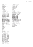
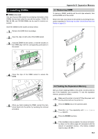
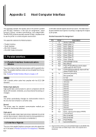
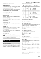
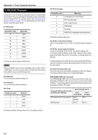
Appendix C Host Computer Interface 3. RS-232C Protocol A protocol is a set of rules the computer follows in sending data to the printer. They are indicated on the status page. Parameters can be changed from the operator panel. See Changing Serial Interface Modes on page 3-19. The parameters and their identification codes are given below. H1: Baud rate Parameter value 12 24 48 96 19 38 57 11 Baud rate 1200 2400 4800 9600 19200 38400 57600 115200 The factory default setting is 9600 baud. NOTE Some computers may not be compatible with a baud rate of 115200 bps. If you set the baud rate to 115200 and communication problems occur, lower the baud rate. H2: Data bits 7 or 8; the factory default setting is 8. H3: Stop bits 1 or 2; the factory default setting is 1. H4: Parity Parameter value 0 1 2 3 Meaning None Odd Even Ignore The factory default setting is None (0 on the status printout). H5: Protocol logic Parameter value Meaning 0 Combination of 1 and 3 below 1 DTR, positive logic 2 DTR, negative logic 3 XON/XOFF 4 ETX/ACK 5 XON/XOFF recognized only as protocol The factory default setting is 0. H6: Buffer nearly-full threshold This is a percentage from 0 to 99. The factory default setting is 90. H7: Buffer nearly-empty threshold This is a percentage from 0 to 99. The factory setting is 70. The factory default settings of the buffer nearly-full and nearlyempty thresholds (H6 and H7) are subject to change without notification. The gap between the nearly-full and nearly-empty thresholds allows the computer to send a fairly large amount of data in a continuous stream. H8: Received-data buffer size This is the size of the input buffer, specified in units of 10 Kbytes. The factory default setting is 6, meaning 60 Kbytes. PRESCRIBE FRPO D0 command The PRESCRIBE FRPO D0 command is provided to allow manipulating XON/XOFF when an error has occurred on the serial interface. The following table summarizes the error status corresponding to different D0 values. Timing of XON transfer to host while Ready or Waiting Serial interface error Error Error not handled handled XON sent every 3 to 5 seconds D0=0 (default) D0=1 XON not sent D0=10 D0=11 C-3
-
 1
1 -
2
-
3
-
4
-
5
-
6
-
7
-
8
-
9
-
10
-
11
-
12
-
13
-
14
-
15
-
16
-
17
-
18
-
19
-
20
-
21
-
22
-
23
-
24
-
25
-
26
-
27
-
28
-
29
-
30
-
31
-
32
-
33
-
34
-
35
-
36
-
37
-
38
-
39
-
40
-
41
-
42
-
43
-
44
-
45
-
46
-
47
-
48
-
49
-
50
-
51
-
52
-
53
-
54
-
55
-
56
-
57
-
58
-
59
-
60
-
61
-
62
-
63
-
64
-
65
-
66
-
67
-
68
-
69
-
70
-
71
-
72
-
73
-
74
-
75
-
76
-
77
-
78
-
79
-
80
-
81
-
82
-
83
-
84
-
85
-
86
-
87
-
88
-
89
-
90
-
91
-
 92
92 -
 93
93 -
 94
94 -
 95
95 -
 96
96 -
 97
97 -
 98
98 -
 99
99 -
 100
100 -
 101
101 -
 102
102 -
103
-
104
-
105
-
106
-
107
-
108
-
109
-
110
-
111
-
112
-
113
-
114
-
115
-
116
-
117
-
118
-
119
-
120
-
121
-
122
-
123
-
124
-
125
-
126
-
127
-
128
-
129
-
130
-
131
-
132
-
133
-
134
-
135
-
136
-
137
-
138
-
139
-
140
-
141
-
142
-
143
 |
 |