Sanyo VCC-HD5400 VCC-HD5400 Manual
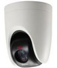
Sanyo VCC-HD5400 - Full HD 1080p Day/Night Pan-Tilt-Zoom Camera Manual
 |
UPC - 086483075698
View all Sanyo VCC-HD5400 manuals
Add to My Manuals
Save this manual to your list of manuals |
Sanyo VCC-HD5400 manual content summary:
- Sanyo VCC-HD5400 | VCC-HD5400 Manual - Page 1
VCC-HD5400/HD5400P Features of This Camera Specifications Target size and recording time Connection and setting of this camera Introduction1/15 - Sanyo VCC-HD5400 | VCC-HD5400 Manual - Page 2
associated software applications on your PC further extends the capabilities of your surveillance system. H.264 Plug-in (supplied): Surveillance video can be viewed in H.264 format. Auto IP Setup (supplied): Downloader (supplied): This searches your local network for cameras and allows IP - Sanyo VCC-HD5400 | VCC-HD5400 Manual - Page 3
boosting Electronic shutter Iris Camera settings AGC gain Gamma correction VCC-HD5400P: 1/25, 1/50, 1/120, 1/250, 1/500, 1/1000, 1/2000, 1/4000, 1/10000 VCC-HD5400: 1/30, 1/60, 1/100, 1/250, 1/500, 1/1000, 1/2000, 1/4000, 1/10000 Long exposure shutter (1×, 2×, 4×, 8×, 16×, 32×) AUTO/MANUAL - Sanyo VCC-HD5400 | VCC-HD5400 Manual - Page 4
Rate Address HD Output: (SDHC compliant, max. 32 GB supported) 4 (NO/NC), also used for sanyo SSP: 1 to 127) SD memory card External HDD Normal recording, alarm recording, backup video recording in event of a network FINE BITRATE mode: User-specified bit rate 10BASE-T/100BASE-TX TCP/IP, UDP, HTTP, - Sanyo VCC-HD5400 | VCC-HD5400 Manual - Page 5
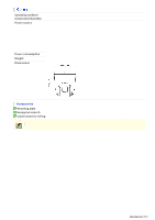
less (no condensation) VCC-HD5400P: 12 to 15 VDC 24 VAC±10%, 50 Hz PoE VCC-HD5400: 12 to 15 VDC 24 VAC±10%, 60 Hz PoE 21 W (PoE: 12.3 W) 1,350 g / 47.6 oz. Unit: mm (inch) Accessories 1 Mounting plate 2 Hexagonal wrench 3 Cable holder for wiring Appearance and specifications are subject to change - Sanyo VCC-HD5400 | VCC-HD5400 Manual - Page 6
function and therefore not displayed on the PDF manual. Refer to the table "Target size and recording time" in the electronic manual. This table is displayed using a browser-specific function and therefore not displayed on the PDF manual. Refer to the table "Target size and recording time" in - Sanyo VCC-HD5400 | VCC-HD5400 Manual - Page 7
refer to the "Connections" section. Connect this terminal to the power supply. Alarm input cable: Connect an external switch, infrared sensor or other alarm device. By connecting a system controller (sold separately), the camera can be controlled remotely. A Audio output terminal (black: 3.5-mm mini - Sanyo VCC-HD5400 | VCC-HD5400 Manual - Page 8
terminals are used, the HD video output terminal takes precedence. To always use the same video terminal, change the [TERMINAL] settings on the VIDEO & AUDIO SETTINGS (TV OUT) screen via network operation. When the camera is turned on, the information on the firmware version and address is displayed - Sanyo VCC-HD5400 | VCC-HD5400 Manual - Page 9
to the installation environment and application of your camera. A Power Connection B Network Connection C Alarm Cable Connection D Connection of attempting to connect each system component, carefully read the instruction manual that comes with it to familiarize yourself with the correct connection procedure - Sanyo VCC-HD5400 | VCC-HD5400 Manual - Page 10
type by ensuring that the voltage at the 24VAC/12-VDC terminal is within the operating range of the camera. If you are using PoE, do not use the camera's power terminals (24 VAC/12 VDC). This camera is designed so that you can use all of its functions via network operation. Introduction 10/15 - Sanyo VCC-HD5400 | VCC-HD5400 Manual - Page 11
port forwarding, please refer to your router's Instruction manual. To connect two or more cameras, on the NETWORK SETTINGS screen, assign them with port numbers that are different from that of the first camera. Using PoE This camera supports PoE (Power over Ethernet). This means that you can install - Sanyo VCC-HD5400 | VCC-HD5400 Manual - Page 12
configure the output conditions for the corresponding alarm output cable via network operation on the ALARM SETTINGS screen. Configuration of alarm output SETTINGS screen. By connecting a system controller (sold separately), the camera can be controlled remotely. Configure the protocol, baud rate and - Sanyo VCC-HD5400 | VCC-HD5400 Manual - Page 13
external hard disk on the camera. Always turn the power off when installing a instruction manual supplied with the hard disk case. If you remove the hard disk drive, be sure to set [HDD] to "NO USE" on the SD/HDD screen before removal. If you have connected the system controller to the camera - Sanyo VCC-HD5400 | VCC-HD5400 Manual - Page 14
protocol is set to "PELCO", set to 2400. 2 Protocol Select the protocol for controlling the camera. Protocol Switch 4 Corresponding Protocol SSP (SANYO) OFF Automatic switching between Sanyo SSP and high speed SSP PELCO ON Automatic switching between PELCO-D and PELCO-P 3 Terminator If you - Sanyo VCC-HD5400 | VCC-HD5400 Manual - Page 15
When protocol is "SSP (SANYO)": Configurable addresses: 1 to 127 Switch 8 is configured to "OFF". When protocol is "PELCO": Configurable addresses: 1 to 255 To configure the address to a number between 128 and 255, set the switch 8 to "ON". List of Address Configuration Switches Introduction 15/15 - Sanyo VCC-HD5400 | VCC-HD5400 Manual - Page 16
VCC-HD5400/HD5400P Preparing Your Computer for Network Operation Setting Up IP Addresses Automatically (Auto IP Setup) Check your operating environment Configue the network information on your PC Operation Privileges and Login Users Before You Begin Network Operation1/13 - Sanyo VCC-HD5400 | VCC-HD5400 Manual - Page 17
to the linked information. 1 Assign a unique IP address to each camera. If you have newly installed two or more cameras on your network, you can accomplish this by using the supplied "Auto IP Setup" software. 2 Check your operating environment 3 Connect the camera to the network to which your PC is - Sanyo VCC-HD5400 | VCC-HD5400 Manual - Page 18
cameras (Total and by status) 3 Camera details "Model name", "IP Address", "Port", "SSL", "Camera Title", and "Firmware Version" are not shown if the network board or other hardware is not supported. "IP Address", "Port", "SSL", and "Camera Title" are editable. (Refer to the "Manually Setting Up IP - Sanyo VCC-HD5400 | VCC-HD5400 Manual - Page 19
It skips any IP address that is already used. If you find that the searched cameras have overlapping IP addresses (indicated by a status of "CAUTION") or if you need to change a camera title, you can edit the displayed camera data manually as described below. Before You Begin Network Operation 4/13 - Sanyo VCC-HD5400 | VCC-HD5400 Manual - Page 20
1 Select the desired camera and click Manual setting . The camera information dialog box opens. 2 Make changes to the camera data and click EXECUTE . This transmits your changes to the camera. You can see the problem of IP address overlap has been resolved in the [Status] row of the list, which has - Sanyo VCC-HD5400 | VCC-HD5400 Manual - Page 21
and browser up-to-date. Note, however, that Internet Explorer 8 is not supported. In the cases below, configure the Internet Explorer's settings by clicking [Tool] and then [Internet Options]. When accessing the camera using SSL encryption for video signal transmission 1 Click the [Advanced] tab - Sanyo VCC-HD5400 | VCC-HD5400 Manual - Page 22
1 In [Control Panel], click [Network and Internet Connections]. The [Network and Internet Connections] dialog box opens. 2 Click [Network Connections]. The [Network Connections] dialog box opens. Under [LAN or High-Speed Internet], the icon representing your LAN interface (Ethernet adapter) - Sanyo VCC-HD5400 | VCC-HD5400 Manual - Page 23
[Internet Protocol (TCP/IP)] check box. Confirm that the [Internet Protocol (TCP/IP)] check box is selected. If deselected, select the check box. 5 Click [Properties]. The [Internet Protocol (TCP/IP) Properties] dialog box opens, with the [General] tab shown. Before You Begin Network Operation 8/13 - Sanyo VCC-HD5400 | VCC-HD5400 Manual - Page 24
subnet mask, and the default gateway. 7 Check the configured settings and click OK . You are now done with the TCP/IP configuration. Close all the dialog boxes that are open. 1 In [Control Panel], click [Network and Sharing Center]. The [Network and Sharing Center] dialog box opens. Before You Begin - Sanyo VCC-HD5400 | VCC-HD5400 Manual - Page 25
2 Click [Manage network connections]. The [Network Connections] dialog box opens. 3 Double-click [Local Area Connection]. The [Local Area Connection Status] dialog box opens. Version 4 (TCP/IPv4)] check box is selected. If deselected, select the check box. Before You Begin Network Operation 10/13 - Sanyo VCC-HD5400 | VCC-HD5400 Manual - Page 26
Properties]. The [Internet Protocol Version 4 (TCP/IPv4) Properties] dialog box opens, with the [General] tab shown. 7 Select the [Use the following IP address:] radio button and specify the IP address and the subnet mask. 8 Check the configured settings and click OK . You are now done with the TCP - Sanyo VCC-HD5400 | VCC-HD5400 Manual - Page 27
□ - - - PTZ controller ○ ○ ○ - - Remote Alarm Buttons ○ ○ ○ - - Emergency recording button ○ ○ ○ - - Downloading data recorded on camera to PC - - - - ○ ○ : Available □: Available (Excluding NETWORK SETTINGS) -: Unavailable △: Available only if permitted by a user with the - Sanyo VCC-HD5400 | VCC-HD5400 Manual - Page 28
your Web browser. However, if the user who is using the software configures one of the following settings, the Web-based admin user will be disconnected from the camera. Camera Setting Normal Recording & Live Setting (JPEG) Live Setting (H.264) Alarm Setting Before You Begin Network Operation 13/13 - Sanyo VCC-HD5400 | VCC-HD5400 Manual - Page 29
VCC-HD5400/HD5400P Access the camera from your Web browser. Live Screen Components Control panel Tool panel Information bar Working with Live Screen1/18 - Sanyo VCC-HD5400 | VCC-HD5400 Manual - Page 30
address is already being used by another device in the network. If so, change the IP address of the existing device before accessing the camera. 3 Type your user name and password and click OK . The language selection screen appears. When you access the camera for the first time, login as an admin - Sanyo VCC-HD5400 | VCC-HD5400 Manual - Page 31
PC the capability to simultaneously access two or more cameras and monitor live video from all connected cameras on a multi-view screen. Recording software "VA-SW3050Server/Client" (Optional) This software is higher-grade software than "VA-SW3050Lite" that adds recording and playback capabilities - Sanyo VCC-HD5400 | VCC-HD5400 Manual - Page 32
When you access and log into the camera successfully, the live screen appears. For details, refer to the linked information. Video display area ( A ) Control Panel ( B ) Tool Panel ( C ) Information Bar ( D ) 1 Current date and time - Sanyo VCC-HD5400 | VCC-HD5400 Manual - Page 33
Image centering operation Clicking the video image changes the camera's orientation so that the point where you click is located at the center of the image. Working with Live Screen 5/18 - Sanyo VCC-HD5400 | VCC-HD5400 Manual - Page 34
purpose. For details, refer to the linked information. A PTZ operation section: You can use the controls on this section B CLIENT SETTINGS : Click this to select the live stream and streaming protocol for each user. C MENU : Click this to display the configuration menu. D LANGUAGE : Click this to - Sanyo VCC-HD5400 | VCC-HD5400 Manual - Page 35
. button Click the buttons to adjust the focus. (NEAR): Focus on a near object (FAR): Focus on a distant object (AUTO FOCUS): Automatic focus The camera lens orientation can be changed by dragging or clicking the mouse on the screen. Drag operation Operate as though using a joy stick for pan - Sanyo VCC-HD5400 | VCC-HD5400 Manual - Page 36
the cursor moves further from the center. Click Operation Drag the mouse to move the cursor on the screen, thereby changing the orientation of the camera lens. When the mouse button is released, the cursor returns to the middle of the screen. Clicking a button will start the corresponding auto mode - Sanyo VCC-HD5400 | VCC-HD5400 Manual - Page 37
be shown to the users without "admin" privilege, if [STREAM SET] is set to "admin" on the USER REGISTRATION screen. You camera supports bidirectional audio communications, so you can send and receive audio between the camera and your PC. Hearing sounds from camera Sending audio messages to camera - Sanyo VCC-HD5400 | VCC-HD5400 Manual - Page 38
click SET . This causes the client PC to start up with the audio output capability enabled when connected to the camera, so that the user can hear sounds from the camera. Setting [AUDIO (CAMERA to PC)] to "OFF" causes the Receive Audio button and the volume control to disappear from the tool panel - Sanyo VCC-HD5400 | VCC-HD5400 Manual - Page 39
menu will not be shown to the users without "admin" previlege, if [PASSWORD SET] is set to "admin" on the USER REGISTRATION screen. Update your password periodically for and application of your camera. Required operation privilege: admin, operator1 ("admin" only for NETWORK SETTINGS screen) Without - Sanyo VCC-HD5400 | VCC-HD5400 Manual - Page 40
14 Configuration Screen (Menu) Operation NETWORK SETTINGS Configure the network settings of the camera. CLOCK SETTINGS Configure the clock date/time, daylight saving mode, automatic clock adjustment, and other settings. USER REGISTRATION Register new login users, or change or delete existing - Sanyo VCC-HD5400 | VCC-HD5400 Manual - Page 41
When the language selection screen appears, select the desired language within 10 seconds. Otherwise, you will be brought back to the live screen with the previous language setting. Click DISPLAY on the control panel to display the image size adjustment panel. : Panel is minimized. Clicking the - Sanyo VCC-HD5400 | VCC-HD5400 Manual - Page 42
camera title is "Network Camera". The color of the camera title changes depending on the alarm state as follows: Black: Normal state Red: Alarm condition is being detected. When the camera this button to send audio messages from the PC to camera. For details, refer to the "Configuring audio" section - Sanyo VCC-HD5400 | VCC-HD5400 Manual - Page 43
if you find any suspicious person or entity during monitoring to record the video on the camera. For details, refer to "Manually Recording Surveillance Video". Click this button to disconnect your PC from the camera and close the browser window. You can capture and then save or print the desired - Sanyo VCC-HD5400 | VCC-HD5400 Manual - Page 44
one of the remote alarm buttons (shown in gray). The button turns orange and an alarm signal is output from the corresponding terminal. If the camera alarm output cable is connected to a buzzer or other external device, alarm sound will be output from the connected device. A : Sends an alarm signal - Sanyo VCC-HD5400 | VCC-HD5400 Manual - Page 45
the REC button, recording stops even during the recording time; however, the [DURATION] settings will be reset. Manual Stop This is available in the case where [DURATION] is configured to "MANUAL". Click the emergency recording button (red) to stop recording. The button returns to grey. Working with - Sanyo VCC-HD5400 | VCC-HD5400 Manual - Page 46
When an error, warning or alarm, etc. occurs, the corresponding status is displayed in red. 1 INFO: Appears when an error or warning occurs. Clicking the indicator label causes system information to appear in a separate window. The INFO status indicator appears in orange until either of the - Sanyo VCC-HD5400 | VCC-HD5400 Manual - Page 47
VCC-HD5400/HD5400P NETWORK SETTINGS CLOCK SETTINGS USER REGISTRATION VIDEO & AUDIO SETTINGS CAMERA SETTINGS PAN/TILT ALARM SETTINGS RECORDING SD/HDD E-MAIL SETTINGS FTP SETTINGS SECURITY SETTINGS SCHEDULE SETTINGS OPTION SETTINGS Working with Administrator Configuration Screens1/79 - Sanyo VCC-HD5400 | VCC-HD5400 Manual - Page 48
administrator. Configure the environment required to connect to the camera via the network by specifying the IP address, subnet mask, and other information. 1 In [IP ADDRESS], select "FIX" and type the IP address of the camera below it. 2 In [SUBNET MASK] and [GATEWAY], type your subnet mask and - Sanyo VCC-HD5400 | VCC-HD5400 Manual - Page 49
name, instead of the IP address of the camera. To use the DDNS service, configure the following settings. Specify your DNS server address under [DNS SETTINGS] on this screen. Configure the port forwarding on your router. (For details, refer to your router's instruction manual.) 1 In [DDNS], select - Sanyo VCC-HD5400 | VCC-HD5400 Manual - Page 50
the steps below to register your domain name. 1 On the LOG IN screen, enter the user name and password you wrote down and click Login . The Domain Name registration/change screen appears. SANYO DDNS service site URL: https://www.ddns-sanyosecurity.com 2 Enter the domain name you want to use and - Sanyo VCC-HD5400 | VCC-HD5400 Manual - Page 51
Return to the NETWORK SETTINGS screen ([DDNS]) and, in [DOMAIN NAME], type the domain name you just registered before ".user.ddns-sanyosecurity.com". a security warning dialog box when attempting to access the camera. However, this is not a problem and you can continue the operation by clicking [Yes - Sanyo VCC-HD5400 | VCC-HD5400 Manual - Page 52
3874 and 5000, between 9874 and 10000, between 38087 and 38214, and between 49026 and 49152). If you intend to access the camera from video viewer or similar software, you may name each stream (access name) as you like for easy identification. 1 Under [ACCESS NAME (JPEG)], type an access name for - Sanyo VCC-HD5400 | VCC-HD5400 Manual - Page 53
The multicast RTP port (video and audio) numbers must be even numbers in the range of 1026 to 65534 that do not overlap with the unicast RTP port numbers (except for numbers between 4000 and 5000, 10000, 10001, 38214, and 49152.) The multicast TTL must be specified in the range of 1 to 255. Working - Sanyo VCC-HD5400 | VCC-HD5400 Manual - Page 54
Click CLOCK in the configuration menu to display the CLOCK SETTINGS screen. Before you start network operation, you need to configure the clock settings on this screen. A Configuring camera title B Configuring clock date/time and display style C Configuring time zone and daylight saving mode D - Sanyo VCC-HD5400 | VCC-HD5400 Manual - Page 55
[TIME ZONE] setting, you can change it manually. NO USE: Disables the daylight saving mode. PC (PC): when an admin user logs into it. ALARM IN1: camera is connected to the Internet. If the camera is not connected to the Internet, select "LOGIN (PC)" or, using the supplied monitoring software - Sanyo VCC-HD5400 | VCC-HD5400 Manual - Page 56
REFRESH . 3 In [NTP SERVER ADDRESS], type the IP address or domain name of the NTP server from which the clock in the following timings. When the camera is turned on At the time selected in DNS server address in [DNS SERVER ADDRESS] on the NETWORK SETTINGS screen. 1 In [CLOCK ADJUST], select "ALARM - Sanyo VCC-HD5400 | VCC-HD5400 Manual - Page 57
guest). For these factory default users, you can change the password only. B [ANONYMOUS USER LOG IN] pull-down menu Use this pull-down menu to enable/disable anonymous user login. Selecting "ON" allows all users to log into the camera without authentication. Working with Administrator Configuration - Sanyo VCC-HD5400 | VCC-HD5400 Manual - Page 58
password again. You can type 4 to 32 alphanumeric characters. 3 In [LIVE STREAM], select the check box next to the stream you want to allow this user to monitor. You may select two or more check boxes. You need to configure the video conditions for each stream on the VIDEO & AUDIO SETTINGS - Sanyo VCC-HD5400 | VCC-HD5400 Manual - Page 59
click SET . Your changes are saved and reflected in the user list. Select the check box next to the user you want to delete and click DELETE . The selected user is deleted from the user list. You cannot delete the factory default users (admin, operator1, operator2, download, and guest). Working with - Sanyo VCC-HD5400 | VCC-HD5400 Manual - Page 60
and click SET . If you configure to "OFF", you can only view the video streams and cannot record them. Clicking SET reboots the camera. This camera supports multi-stream video transmission, allowing you to register up to four video/image streaming condition patterns. Thus, you can reduce the load of - Sanyo VCC-HD5400 | VCC-HD5400 Manual - Page 61
configurable settings may be affected by other stream settings. The camera provides two factory default stream patterns (STREAM1 and STREAM2. RECORDING], select the recording type. OFF: NORMAL: ALARM: NORMAL/ALARM: NETWORK FAILURE: No recording Normal live video is recorded. Alarm video is recorded - Sanyo VCC-HD5400 | VCC-HD5400 Manual - Page 62
on your selection in [CODEC] and your camera model. JPEG: VCC-HD5400: 0.1ips, 0.2ips, 0.5ips, 1ips, 3ips, 5ips, 10ips, 15ips, 30ips VCC-HD5400P: 0.1ips, 0.2ips, 0.5ips, 1ips, 2.5ips, 5ips, 8ips, 12.5ips, 25ips H.264: VCC-HD5400: 5ips, 10ips, 15ips, 30ips VCC-HD5400P: 5ips, 8ips, 12.5ips, 25ips 8 In - Sanyo VCC-HD5400 | VCC-HD5400 Manual - Page 63
. 2 Change the desired settings and click SET . Your changes are saved and reflected in the stream list. 3 Click SET in the stream list. The camera restarts, and the changed settings are applied. 1 Select the check box next to the stream you want to delete and click DELETE . The selected stream - Sanyo VCC-HD5400 | VCC-HD5400 Manual - Page 64
specify the microphone sensitivity. Select the sensitivity of the microphone connected to the camera from 8 levels. +4, +3, +2, +1, 0, -1, -2, -3 3 In amplifier from the following 4 levels. +2, +1, 0, -1 5 To mute audio output during PTZ operation, set [MUTE (PAN/TILT, ZOOM)] to "ON" and click SET . - Sanyo VCC-HD5400 | VCC-HD5400 Manual - Page 65
2 In [SIGNAL FORMAT], select the video size. VCC-HD5400: 1080i, 720p, 480p VCC-HD5400P: 1080i, 720p, 576p You can select [SIGNAL FORMAT position name, etc. are displayed on the monitor and the live screen via the network. 4 In [DISPLAY POSITION], set the OSD display position, and then click SET - Sanyo VCC-HD5400 | VCC-HD5400 Manual - Page 66
one of the menu items in the sub menu to jump to the desired camera setting screen. 2 DEFAULT : Click this button to reset all the settings Initialize the lens focus and zoom settings. This area shows a series of camera settings. You can use the vertical scroll bar and scroll buttons to scroll the - Sanyo VCC-HD5400 | VCC-HD5400 Manual - Page 67
views. You can view how your changes affect the video image in real time. You can configure eight patterns of monitoring conditions (camera views). For example, select "CAM1" to configure the normal live monitoring conditions for daytime use and select "CAM2" to configure the monitoring conditions - Sanyo VCC-HD5400 | VCC-HD5400 Manual - Page 68
of the target object. AUTO: Selects the auto iris mode. MANUAL: Selects the manual iris mode. The configured settings are applied only to the camera views that were specified in [VIEW]. Configuring these settings enables the camera to automatically adjust the lens iris to reproduce natural images - Sanyo VCC-HD5400 | VCC-HD5400 Manual - Page 69
use the electronic iris, configure the lens iris manually using the following procedure. 1 In [IRIS], select "MANUAL". 2 In [EI], enable or disable the . In this case, configure the auto iris. Under fluorescent lighting, the camera may cause the target image to flicker. To prevent this, replace the - Sanyo VCC-HD5400 | VCC-HD5400 Manual - Page 70
white balance (for outdoors) FLUORESCENT: Selects the Fixed white balance mode (for fluorescent lighting). MWB: Manual white balance The configured settings are applied only to the camera views that were specified in [VIEW]. Auto trace white balance (ATW) automatically adjusts the white balance - Sanyo VCC-HD5400 | VCC-HD5400 Manual - Page 71
. AWC allows you to automatically adjust the white balance by simply clicking SET with the camera lens directed toward a white wall, white paper and the like. 1 In [WHITE BALANCE], select "AWC". 2 Direct the camera lens toward a white wall, white paper and the like and, in [AWC LOCK], click SET - Sanyo VCC-HD5400 | VCC-HD5400 Manual - Page 72
For fluorescent lighting (Fixes the color temperature to 4200K.) Use the following procedure to manually adjust the gain values for the red and blue signals. 1 In [WHITE the camera views that were specified in [VIEW]. Multi-spot evaluative metering compensates for the backlighting problem by - Sanyo VCC-HD5400 | VCC-HD5400 Manual - Page 73
backlighting and click SET . 0 (low brightness compensation) to 15 (high brightness compensation) Center-weighted average metering compensates for the backlighting problem by measuring the photometry of the specified area intensively. Configure the position and size of the center metering area. 1 In - Sanyo VCC-HD5400 | VCC-HD5400 Manual - Page 74
area and therefore does not affect the actual live video image from the camera. 5 Click SET and then BACK . The settings are saved and to the sub menu. You can use light source masking to compensate for backlighting problems with human or other objects in the subject, by masking the light source in - Sanyo VCC-HD5400 | VCC-HD5400 Manual - Page 75
SHUTTER] is set to "SHORT" or "LONG". [IRIS] is set to "MANUAL". Configure the electronic shutter according to the movement and luminance level of the target object exposure shutter mode. The configured settings are applied only to the camera views that were specified in [VIEW]. The fast shutter mode - Sanyo VCC-HD5400 | VCC-HD5400 Manual - Page 76
SHUTTER SPEED], select the desired shutter speed and click SET . VCC-HD5400P: 25, 50, 120, 250, 500, 1000, 2000, 4000, 10000 VCC-HD5400: 30, 60, 100, 250, 500, 1000, 2000, Manually configuring gain value Auto Gain Control (AGC) is a function that automatically adjusts the gain value of the camera's - Sanyo VCC-HD5400 | VCC-HD5400 Manual - Page 77
In [AGC], select "ON". 2 In [MAX GAIN], select the maximum gain level for AGC and click SET . Selecting a higher gain level will improve the camera sensitivity in a dark condition, but increase the noise as well. NORMAL: For normal subject MIDDLE: For slightly dark subject HIGH: For dark subject The - Sanyo VCC-HD5400 | VCC-HD5400 Manual - Page 78
" and "HIGH". LOW: ADJ: Sets a low luminance level (to increase the time during which the camera operates in the color mode). Enables the manual adjustment of the luminance level. Manually Configuring Mode-Switching Luminance Level (ADJ) You can select a luminance level between 1 and 7 for both - Sanyo VCC-HD5400 | VCC-HD5400 Manual - Page 79
to configure the signal polarity in [POLARITY] under [ALARM IN1] to [ALARM IN4] on the ALARM SETTINGS screen. Depending on the [POLARITY] setting, the camera will be switched between the color and black-andwhite video modes as follows (commonly applied to CAM1 and CAM2): If [POLARITY] is set to "NO - Sanyo VCC-HD5400 | VCC-HD5400 Manual - Page 80
[LEVEL] and click SET . The higher the correction level, the greater the correction effect. 1 to 15 The configured settings are applied only to the camera views that were specified in [VIEW]. Use the color saturation compensation function to improve the vividness of the color. In [VIVID COLOR EFFECT - Sanyo VCC-HD5400 | VCC-HD5400 Manual - Page 81
"ON" and click SET . The configured settings are applied only to the camera views that were specified in [VIEW]. Enabling the DNR function may cause ghosts . Configure the auto or manual focusing mode. AUTO: Selects the auto focus mode. MANUAL: Selects the manual focus mode (Sets the focusing - Sanyo VCC-HD5400 | VCC-HD5400 Manual - Page 82
, select to "LOW". 4 In [AREA], select the auto focusing area. FULL: Full screen CENTER(LARGE): Selects the center of screen (larger area) CENTER(SMALL): passed. AUTO: Returns the camera to the auto focus mode when the zoom operation is performed after manual focusing. Working with Administrator Configuration - Sanyo VCC-HD5400 | VCC-HD5400 Manual - Page 83
FOCUS], select "MANUAL". 2 In settings. The configured settings are applied in common to all the camera views. 1 In [SPEED], select the optical zoom speed. [EL ZOOM], select the electronic zoom magnification power. The optical zoom provides a maximum magnification power of ×10. If you need a zoom - Sanyo VCC-HD5400 | VCC-HD5400 Manual - Page 84
OFF, and click SET . The configured settings are applied only to the camera views that were specified in [VIEW]. You cannot configure [MOTION], if the is enabled. You can configure the privacy mask settings to hide specific portions of surveillance video for privacy protection. When a privacy mask - Sanyo VCC-HD5400 | VCC-HD5400 Manual - Page 85
. 1 Click [PRIVACY MASK] in the sub menu. The PRIVACY MASK SETTINGS screen appears. 2 Click PTZ to view the PTZ controller. 3 Use the controller to adjust the orientation of the camera lens while monitoring live video displayed on the monitor. 4 Click the mask number button you want to configure - Sanyo VCC-HD5400 | VCC-HD5400 Manual - Page 86
6 Check the boxes you want to configure. Select a mask number check box by clicking the corresponding mask number button to activate the corresponding mask pattern and display it on the live screen. You may select two or more check boxes. 7 In [COLOR], select the color of the mask pattern(s). BLACK, - Sanyo VCC-HD5400 | VCC-HD5400 Manual - Page 87
well as the optional functions for panning/tilting. A Live video: You can confirm the orientation of the camera lens and the zoom conditions or other functions. B PTZ button: Click this button to display the PTZ controller. You can use the control panel in the same manner as that on the live video - Sanyo VCC-HD5400 | VCC-HD5400 Manual - Page 88
limit angle. OFF, -20, -18, -16, -14, -12, -10, -8, -6, -4, -2, 0, 2, 4, 6, 8, 10, 12, 14, 16, 18, 20, 22 MANUAL: You can select any value from among above options for the limit angle, while tilting the camera to view actual video images. If a preset position was set beyond the limit angle you have - Sanyo VCC-HD5400 | VCC-HD5400 Manual - Page 89
: The camera is moving in the automatic mode or by means of the preset function. The camera is panning or tilting through manual operation. You orientation of camera lens, the conditions of focus and zoom, and the operation conditions as preset positions. You can also use the PTZ controller to - Sanyo VCC-HD5400 | VCC-HD5400 Manual - Page 90
to view the PTZ controller. 2 Use the controller to adjust the orientation of the camera lens and the condition of focus or zoom, while monitoring live video displayed on the monitor. 3 Specify each item for [PRESET NUMBER.1] and click SET . The orientation of camera lens, the conditions of focus - Sanyo VCC-HD5400 | VCC-HD5400 Manual - Page 91
then YES in the confirmation dialog box. Every setting such as the orientation of the camera lens will be returned to the factory default setting. Click SET in [AUTO MODE returning to a monitoring condition specified (AUTO RETURN). The camera moves on to the next preset position one after another - Sanyo VCC-HD5400 | VCC-HD5400 Manual - Page 92
To use this function, on the PRESET POSITION SETTINGS screen, register preset positions which you want to monitor in sequence in the same groupe. 1 In [SEQUENCE], select "1". 2 Configure the monitoring sequence STEP: Moves in the numerical order of preset positions. RANDOM: Moves in a random manner - Sanyo VCC-HD5400 | VCC-HD5400 Manual - Page 93
specified tilt, focus and zoom conditions. Auto focus works only when the camera moves slowly or it pauses at the end point for more than five patterns of sequential operations such as panning, tilting and zooming. 1 Click PTZ to view the PTZ controller. 2 Select "1" for [TOUR]. 3 Click START , and - Sanyo VCC-HD5400 | VCC-HD5400 Manual - Page 94
format of "n/100". Recording stops automatically when memory reaches full, indicating "100/100". 5 Once the operation is finished the specified operation. If there is no user operation for a certain length of time, this is powered off while waiting for auto return, an auto return mode that was - Sanyo VCC-HD5400 | VCC-HD5400 Manual - Page 95
] on the RECORDING screen. Configure the input condition of the camera alarm input cable and the corresponding behavior for each alarm input number. To configure this function, connect an alarm input cable for the camera. For details, refer to the "Alarm Cable Connection" section. 1 Select - Sanyo VCC-HD5400 | VCC-HD5400 Manual - Page 96
the last alarm received. If the system is powered off while an alarm action is taking place, PTZ operation and for a specific time after the operation, select the alarm-disabled period after PTZ , 6MIN, 7MIN, 8MIN, 9MIN, 10MIN This camera offers the built-in motion sensor function that automatically - Sanyo VCC-HD5400 | VCC-HD5400 Manual - Page 97
pursuit function after enabling the motion sensor, the motion sensor will be forcibly disabled. Use the motion detection function to detect motion in specific areas of the subject. 1 On the ALARM SETTINGS screen, in [MOTION], select "DETECT". 2 In [DURATION], select how long you want the alarm state - Sanyo VCC-HD5400 | VCC-HD5400 Manual - Page 98
to view the PTZ controller. 4 Use the controller to adjust the orientation of the camera lens while monitoring live The detection area is configured over the specified area. While changing the orientation of the camera lens, you can set up to 32 detection areas to anywhere in the whole monitored - Sanyo VCC-HD5400 | VCC-HD5400 Manual - Page 99
8 In [SENSITIVITY], select the detection sensitivity. You can adjust the detection sensitivity to prevent unwanted detection. The higher the value, the lower the sensitivity. 1 (HIGH) to 9 (LOW) 9 In [FACE DETECTION], select "ON" to use the face detection function. The face detection function judges - Sanyo VCC-HD5400 | VCC-HD5400 Manual - Page 100
1 On the ALARM SETTINGS screen, in [MOTION], select "ANALYTICS". 2 In [DURATION], select how long you want the alarm state to be retained when the motion sensor detects motion and click DETAIL . The ANALYTICS screen appears. 5SEC, 10SEC, 15SEC, 20SEC, 30SEC, 45SEC, 1MIN, 2MIN, 3MIN, 4MIN, 5MIN CC ( - Sanyo VCC-HD5400 | VCC-HD5400 Manual - Page 101
You can draw up to eight detection lines. Each detection line has a serial number (1 to 8) and area designations (A and B). 2 Setting detection areas Select the radio button next to [AREA] and drag the mouse to draw detection areas. You can draw up to four detection areas. Each detection area has a - Sanyo VCC-HD5400 | VCC-HD5400 Manual - Page 102
outputs an alarm signal when the output: corresponding Remote Alarm button is clicked. If you configure this function, connect an alarm output cable for the camera. For details, refer to the "Alarm Cable Connection" section. Working with Administrator Configuration Screens 56/79 - Sanyo VCC-HD5400 | VCC-HD5400 Manual - Page 103
1 Select "ON" for [ALARM OUT1] . 2 In [POLARITY], select the signal polarity of the alarm output terminal. NO (Normally Open): The terminal is normally open and closes when an alarm signal is output. NC (Normally Closed): The terminal is normally closed and opens when an alarm signal is output. 3 In - Sanyo VCC-HD5400 | VCC-HD5400 Manual - Page 104
3 In [ALARM OUT TIME], select how long you want the terminal to output the alarm signal and click SET . The terminal will stop outputting the alarm signal when the set alarm output time expires. 2SEC, 5SEC, 10SEC, 15SEC, 30SEC, 45SEC, 1MIN, 2MIN, 3MIN, 4MIN, 5MIN CC (Stops outputting the alarm - Sanyo VCC-HD5400 | VCC-HD5400 Manual - Page 105
See the description of [ALARM EVENT] (step 4 ) for details on [FRAME RATE], [PRE ALARM] and [DURATION]. A NETWORK FAILURE This is the time from the occurrence of a network failure until the camera recognizes it as a trigger. 15SEC, 20SEC, 30SEC, 40SEC, 50SEC, 1MIN, 2MIN, 3MIN, 4MIN, 5MIN The setting - Sanyo VCC-HD5400 | VCC-HD5400 Manual - Page 106
depending on the monitoring purpose of the camera. - Sanyo VCC-HD5400 | VCC-HD5400 Manual - Page 107
the frame rate of the stream. In [FRAME RATE], set the frame rate of the pre-alarm video stream. VCC-HD5400: 0.1ips, 0.2ips, 0.5ips, 1ips, 3ips, 5ips, 10ips, 15ips, 30ips VCC-HD5400P: 0.1ips, 0.2ips, 0.5ips, 1ips, 2.5ips, 5ips, 8ips, 12.5, 25ips Here, you can select a frame rate slower than that set - Sanyo VCC-HD5400 | VCC-HD5400 Manual - Page 108
This button is labeled "SCHEDULE ON" if the recording schedule has been configured. Working with Administrator Configuration Screens 62/79 - Sanyo VCC-HD5400 | VCC-HD5400 Manual - Page 109
respectively. The recorded log information is retained even when the camera power is turned off. 3 In [AREA], allocate the storage network failure. 4 In [SIZE/FORMAT], check that the storage capacity of the SD card ("4GB" for example) is shown. This field shows "NO CARD" or "NO MEDIA" when the camera - Sanyo VCC-HD5400 | VCC-HD5400 Manual - Page 110
overwriting the oldest recorded data if the recording area becomes full. OFF: Disables overwrite recording so that the camera stops recording if the recording area becomes full. If recording stops because the recording area has become full, you can turn [OVERWRITE] to "ON", or secure the recording - Sanyo VCC-HD5400 | VCC-HD5400 Manual - Page 111
network administrator. 1 In [E-MAIL], select "ON" to enable the e-mail transmission function. 2 In [SSL], select "ON" to use SSL communication. If your e-mail server supports you need to do so, change the default value. 4 In [USER MAIL ADDRESS], type the sender's e-mail address and click SET . Here - Sanyo VCC-HD5400 | VCC-HD5400 Manual - Page 112
card error occurrs, Error occurred in the hard disk drive. Abnormal camera temperature Error occurred in the fan When the remaining recording area is recording area had been used up, or When a power failure occurs, or the system recovers from a power failure. Abnormal USB current * To send a - Sanyo VCC-HD5400 | VCC-HD5400 Manual - Page 113
an alarm signal. Sends an e-mail when the camera detects a network failure during network recording. A If you selected "NETWORK FAILURE" ... In [NETWORK FAILURE TIME], select the time from the occurrence of a network failure until the camera recognizes it as a recording trigger. 15SEC, 20SEC, 30SEC - Sanyo VCC-HD5400 | VCC-HD5400 Manual - Page 114
subject and message text portions of the e-mail. An e-mail consists of the following portions. Subject Camera Title Data and time Camera's IP address Message (TEXT) The camera title, date and time, IP address will be included automatically. 1 In [SUBJECT], type the subject (title) of the e-mail. You - Sanyo VCC-HD5400 | VCC-HD5400 Manual - Page 115
If you want to record images from the camera to an FTP server via the network, configure the FTP server settings and the image ). 3 In [SERVER ADDRESS], type the server address. Then, in [USER ID] and [PASSWORD], type the user ID and password, respectively. The number of characters you can type in - Sanyo VCC-HD5400 | VCC-HD5400 Manual - Page 116
jpg] If no file name is specified, the system will enter "sanyo" for the [FILE NAME]. * To use a temporary file, file name. Temporary file name: sanyo_ftp_temp_[IP address].temp Although the temporary file NETWORK FAILURE: Sends a still image when the camera detects a network failure during network - Sanyo VCC-HD5400 | VCC-HD5400 Manual - Page 117
3MIN, 5MIN, 10MIN, 15MIN, 30MIN, 1HOUR, 2HOUR, 3HOUR, 4HOUR, 5HOUR, 6HOUR, 8HOUR, 12HOUR, 24HOUR If you selected "ALARM IN1-4", "MOTION", "ALARM OUT1/2" or "NETWORK FAILURE", only "1SEC" to "15MIN" is displayed as an option. In [INTERVAL], the pull-down menu will only show options that do not exceed - Sanyo VCC-HD5400 | VCC-HD5400 Manual - Page 118
ADDRESS/SUBNET] ( 3 ). AUTHORIZED: Permits access to the camera. REJECTED: Rejects access to the camera. 3 In [NETWORK ADDRESS/SUBNET], configure the access settings for individual PCs. Type the IP address and the subnet mask of each PC and specify whether or not to grant - Sanyo VCC-HD5400 | VCC-HD5400 Manual - Page 119
4 Click SET . The settings are saved. Working with Administrator Configuration Screens 73/79 - Sanyo VCC-HD5400 | VCC-HD5400 Manual - Page 120
END], specify the start and end time of the recording. Configuring the camera to start recording at 1:00 and end recording at 19:00 every Sunday (18 week indication in the [END] column to the next day. Configuring the camera to start recording at 1:00 every Sunday and end recording at 0:50 - Sanyo VCC-HD5400 | VCC-HD5400 Manual - Page 121
settings, be sure to click SET to update the schedule map. If you change the scheduled settings while the schedule is enabled, the camera will perform recording according to the changed schedule. If you schedule overlapping recording periods, the longer one will take precedence. If the configured - Sanyo VCC-HD5400 | VCC-HD5400 Manual - Page 122
You can define up to 20 annual holidays. Example: Defining July 18 as an annual holiday, in addition to weekly holidays (Mondays) defined in [HOLIDAY] 4 Click SET and then BACK . The setting is saved and the HOLIDAY SETTINGS section disappears. Working with Administrator Configuration Screens 76/79 - Sanyo VCC-HD5400 | VCC-HD5400 Manual - Page 123
reason or other, in [CAMERA REBOOT], click SET to reboot the camera system. You can update the camera's firmware to the latest version. 1 Click SET . The FIRMWARE UPDATE screen appears. 2 Click Browse... and select the firmware updater file. 3 Click EXECUTE . The firmware update process starts. When - Sanyo VCC-HD5400 | VCC-HD5400 Manual - Page 124
stop working temporarily. You cannot update the firmware while the camera is recording. In this case, an operation confirmation dialog box will open. You can restore all the settings you have configured to the factory default settings. In [NETWORK SETTINGS], select whether or not to restore - Sanyo VCC-HD5400 | VCC-HD5400 Manual - Page 125
external hard disk drive. A ACCESS LOG Shows the history of access to the camera in chronological order (up to 100 entries). Date and time, user name, authentication check result (OK/NG), connection destination IP address B SYSTEM LOG Shows a history of system operations and errors in chronological - Sanyo VCC-HD5400 | VCC-HD5400 Manual - Page 126
VCC-HD5400/HD5400P Accessing the Camera Control Panel/Tool Panel CAMERA SETTINGS Displaying LIVE video Transmitting Image Data Recording Pan/Tilt Others Q&A1/12 - Sanyo VCC-HD5400 | VCC-HD5400 Manual - Page 127
to access is not a local address. Enter a local address to access a camera located in the same network. You cannot access a camera by entering a URL (or router global address and camera port number) registered with the dynamic DNS service or a URL that is compliant with the global address. I cannot - Sanyo VCC-HD5400 | VCC-HD5400 Manual - Page 128
refer to your router's instruction manual. 5 The IP address you entered is a local address (the one you use at your home). When accessing via Internet, enter the global address (or the URL registered with the DDNS service) and port number of the camera as its IP address. The camera has been suddenly - Sanyo VCC-HD5400 | VCC-HD5400 Manual - Page 129
. In this case, you can change the operation privilege by entering a user name with an adequate operation privilege and its password in the dialog box. The camera responds to neither focus nor zoom operation. Communication between the camera and the PC is down. Click the [Refresh] button on your Web - Sanyo VCC-HD5400 | VCC-HD5400 Manual - Page 130
I cannot set [SHUTTER] to "SHORT" or "LONG". You cannot configure the electronic shutter settings if you have set [SENSE UP] in [IRIS]. Set [SENSE UP] in [IRIS] to "OFF". I cannot turn off the AGC. 1 You cannot set [AGC] to "OFF" when [DAY/NIGHT] is set to "AUTO". Set [DAY/NIGHT] to "COLOR" or - Sanyo VCC-HD5400 | VCC-HD5400 Manual - Page 131
simultaneously accessible users is already reached. 3 The version of the installed plug-in is old. When another plug-in for network cameras is installed, Plug-In you can download from SANYO CCTV System Web page. 4 The Web browser you are using for accessing the camera is configured to connect to the - Sanyo VCC-HD5400 | VCC-HD5400 Manual - Page 132
stops temporarily. 1 Among the multiple accesses to the camera, some are from narrowband networks. Change the minimum bit rate for video streaming to not clear. 1 [FOCUS] for CAMERA is set to [AUTO]. Adjust after setting to [MANUAL]. 2 [FOCUS] for CAMERA is set to [MANUAL]. Change it to [AUTO]. 3 - Sanyo VCC-HD5400 | VCC-HD5400 Manual - Page 133
LIVE video image is noisy. 1 The background of the object is dark. Increase the lighting to the monitored environment. Alternatively, in [DAY/NIGHT] on the CAMERA SETTINGS screen, select [AUTO] to enable the [DAY/NIGHT] mode. 2 The color quality for your PC monitor is configured to less than 16 bits - Sanyo VCC-HD5400 | VCC-HD5400 Manual - Page 134
work. 1 On the E-MAIL SETTING screen, incorrect user ID/password information is specified in the AUTHENTICATION section. Set authentification. Contact your network administrator and change the authentication setting according to the SMTP server setting. This camera supports the two authentication - Sanyo VCC-HD5400 | VCC-HD5400 Manual - Page 135
a recording medium for about 30 seconds after powered on. After turning on the camera, wait 5 minutes or more before starting to camera is not equipped with playback functions. Install the supplied application software "HDC Downloader/ DLViewer" from the supplied CD-ROM. This application software - Sanyo VCC-HD5400 | VCC-HD5400 Manual - Page 136
completes. A preset position loses accuracy. The position of the camera lens might have been changed. Click LENS INITIALIZATION on the CAMERA SETTINGS screen to initialize the lens, turn the unit power off and on again. The camera lens stops at the vertical position (facing ground) during a tilt - Sanyo VCC-HD5400 | VCC-HD5400 Manual - Page 137
been terminated. Upgrade has been interrupted due to power off, network fault, or other problem during the process. Redo the upgrade by proceeding as follows. 1 Turn on the camera again. 2 Access the camera again. 3 Check the firmware version on [FIRMWARE UPDATE] in OPTION SETTINGS screen. * If the - Sanyo VCC-HD5400 | VCC-HD5400 Manual - Page 138
VCC-HD5400/HD5400P Copyright Notice How to use this manual. Others1/8 - Sanyo VCC-HD5400 | VCC-HD5400 Manual - Page 139
This instruction manual is copyrighted by SANYO Electric Co., Ltd. No materials contained in this manual may be reproduced in any format SDHC Logo is a trademark. All other brands and product names in this manual are the registered trademarks or trademarks of their respective owners. The following - Sanyo VCC-HD5400 | VCC-HD5400 Manual - Page 140
must not be used to * endorse or promote products derived from this software without * prior written permission. For written permission, please contact * openssl- (INCLUDING, BUT * NOT LIMITED TO, PROCUREMENT OF SUBSTITUTE GOODS OR SERVICES; * LOSS OF USE, DATA, OR PROFITS; OR BUSINESS INTERRUPTION) - Sanyo VCC-HD5400 | VCC-HD5400 Manual - Page 141
specific code (or a derivative thereof) from * the apps directory (application code) you must include an acknowledgement: * "This product includes software written by Tim Hudson ([email protected])" * * THIS SOFTWARE TO, PROCUREMENT OF SUBSTITUTE GOODS * OR SERVICES; LOSS OF USE, DATA, OR PROFITS; - Sanyo VCC-HD5400 | VCC-HD5400 Manual - Page 142
This window shows a table of contents. The headline of the topic currently opened at the main window is highlighted, so the current location among the manual can be easily confirmed. 2 TITLE window This window shows the headline of the current topic. This TITLE window never scrolls not to hide the - Sanyo VCC-HD5400 | VCC-HD5400 Manual - Page 143
1 Previous/Next Clicking or page, respectively. 2 Page end on the top right of the TITLE window will display the previous page or the next is located at the end of the page. This mark is also linked to the top of the page. Click on this mark to jump to the top of the page. Others 6/8 - Sanyo VCC-HD5400 | VCC-HD5400 Manual - Page 144
restricted operating and setting instructions. This manual uses the following notations to present user-interface related information: NETWORK SETTINGS). Information such as operation buttons and icons are represented as graphics, as displayed on the screen (Example: SET ). The names of specific - Sanyo VCC-HD5400 | VCC-HD5400 Manual - Page 145
The options or values that you select in a pull-down menu or using radio buttons are enclosed in double quotes " " (Example: "ON", "80"). Each section describing a configuration procedure begins with a screenshot of the corresponding initial configuration screen. The purpose of this screenshot is to
-
 1
1 -
 2
2 -
 3
3 -
 4
4 -
 5
5 -
 6
6 -
 7
7 -
8
-
9
-
10
-
11
-
12
-
13
-
14
-
15
-
16
-
17
-
18
-
19
-
20
-
21
-
22
-
23
-
24
-
25
-
26
-
27
-
28
-
29
-
30
-
31
-
32
-
33
-
34
-
35
-
36
-
37
-
38
-
39
-
40
-
41
-
42
-
43
-
44
-
45
-
46
-
47
-
48
-
49
-
50
-
51
-
52
-
53
-
54
-
55
-
56
-
57
-
58
-
59
-
60
-
61
-
62
-
63
-
64
-
65
-
66
-
67
-
68
-
69
-
70
-
71
-
72
-
73
-
74
-
75
-
76
-
77
-
78
-
79
-
80
-
81
-
82
-
83
-
84
-
85
-
86
-
87
-
88
-
89
-
90
-
91
-
92
-
93
-
94
-
95
-
96
-
97
-
98
-
99
-
100
-
101
-
102
-
103
-
104
-
105
-
106
-
107
-
108
-
109
-
110
-
111
-
112
-
113
-
114
-
115
-
116
-
117
-
118
-
119
-
120
-
121
-
122
-
123
-
124
-
125
-
126
-
127
-
128
-
129
-
130
-
131
-
132
-
133
-
134
-
135
-
136
-
137
-
138
-
139
-
140
-
141
-
142
-
143
-
144
-
145
 |
 |
VCC-HD5400/HD5400P
Features of This Camera
Specifications
Target size and recording time
Connection and setting of this camera
Introduction1/15