Sanyo VCC-HD5400 VCC-HD5400 Manual - Page 101
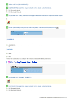
Select the [LINE] radio button and, in the pull-down menu, select the line number 1.
 |
UPC - 086483075698
View all Sanyo VCC-HD5400 manuals
Add to My Manuals
Save this manual to your list of manuals |
Page 101 highlights
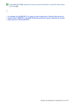
You can draw up to eight detection lines. Each detection line has a serial number (1 to 8) and area designations (A and B). 2 Setting detection areas Select the radio button next to [AREA] and drag the mouse to draw detection areas. You can draw up to four detection areas. Each detection area has a serial number (1 to 4) and area designations (A and B). 3 Configuring detection conditions Select the [LINE] or [AREA] radio button to select a line or area number, and specify detection conditions. To delete a detection line or area, click the [LINE] or [AREA] radio button to select a line or area number, and click DELETE . 1 Select the [LINE] radio button and, in the pull-down menu, select the line number "1". 2 In [SIZE], select the size of the object you want to detect. Specify the size of the object you want to detect. The higher the value, the larger the detectable object size. The detection line (or detection area) is now shown with an image that represents the detection size. Any object larger than this image will be detected. 0 to 5 Selecting "0" means that objects will be detected regardless of their size. In this case, the detection size image is not shown. 3 In [DIRECTION], specify the direction of the object movement you want to detect. The detection line (or detection area) is now shown with an arrow that represents the direction of the object movement to be detected. Working with Administrator Configuration Screens 55/79
-
 1
1 -
2
-
3
-
4
-
5
-
6
-
7
-
8
-
9
-
10
-
11
-
12
-
13
-
14
-
15
-
16
-
17
-
18
-
19
-
20
-
21
-
22
-
23
-
24
-
25
-
26
-
27
-
28
-
29
-
30
-
31
-
32
-
33
-
34
-
35
-
36
-
37
-
38
-
39
-
40
-
41
-
42
-
43
-
44
-
45
-
46
-
47
-
48
-
49
-
50
-
51
-
52
-
53
-
54
-
55
-
56
-
57
-
58
-
59
-
60
-
61
-
62
-
63
-
64
-
65
-
66
-
67
-
68
-
69
-
70
-
71
-
72
-
73
-
74
-
75
-
76
-
77
-
78
-
79
-
80
-
81
-
82
-
83
-
84
-
85
-
86
-
87
-
88
-
89
-
90
-
91
-
92
-
93
-
94
-
95
-
 96
96 -
 97
97 -
 98
98 -
 99
99 -
 100
100 -
 101
101 -
 102
102 -
 103
103 -
 104
104 -
 105
105 -
 106
106 -
107
-
108
-
109
-
110
-
111
-
112
-
113
-
114
-
115
-
116
-
117
-
118
-
119
-
120
-
121
-
122
-
123
-
124
-
125
-
126
-
127
-
128
-
129
-
130
-
131
-
132
-
133
-
134
-
135
-
136
-
137
-
138
-
139
-
140
-
141
-
142
-
143
-
144
-
145
 |
 |
