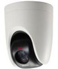
Sanyo VCC-HD5400 VCC-HD5400 Manual - Page 8
Control switch, Address switch - firmware
 |
UPC - 086483075698
View all Sanyo VCC-HD5400 manuals
Add to My Manuals
Save this manual to your list of manuals |
Page 8 highlights
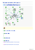
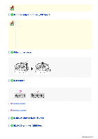
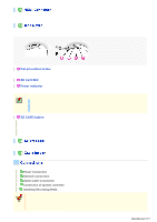
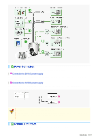
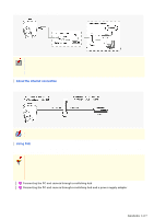
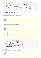
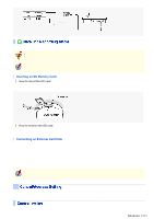
This jack supports 3.5-mm diameter monaural microphone plugs, or monaural line-level input plugs (the left channel only for stereo plugs). Connect this terminal to a monitor, etc. A live video will be displayed on the monitor once the camera is turned on. You cannot output the video simultaneously from HD video output terminal (HDMI) and from monitor output terminal (MONITOR OUT). When both terminals are used, the HD video output terminal takes precedence. To always use the same video terminal, change the [TERMINAL] settings on the VIDEO & AUDIO SETTINGS (TV OUT) screen via network operation. When the camera is turned on, the information on the firmware version and address is displayed on the monitor. The live video displayed on the monitor provides the current pan/tilt angle, zoom magnification and preset position name (or the memory usage when the TOUR operation is set). You can change the display position and other settings on the VIDEO & AUDIO SETTINGS (TV OUT) screen via network operation. If you wire on the ceiling surface, remove the wiring gutter cover. If you have connected the controller to the camera, you must configure necessary settings. For details, refer to the "Control/Address Settings" section. A Control switch Use this switch to configure the baud rate and protocol settings. B Address switch Use this switch to configure the camera control address. Use this socket to connect the camera to your PC to enable network operation. To record video on an external hard disk drive, you must install a 2.5" hard disk (SATA) in the dedicated hard disk case (VA-HDC4000) which is sold separately and then connect the case. Introduction 8/15
-
 1
1 -
2
-
 3
3 -
 4
4 -
 5
5 -
 6
6 -
 7
7 -
 8
8 -
 9
9 -
 10
10 -
 11
11 -
 12
12 -
 13
13 -
14
-
15
-
16
-
17
-
18
-
19
-
20
-
21
-
22
-
23
-
24
-
25
-
26
-
27
-
28
-
29
-
30
-
31
-
32
-
33
-
34
-
35
-
36
-
37
-
38
-
39
-
40
-
41
-
42
-
43
-
44
-
45
-
46
-
47
-
48
-
49
-
50
-
51
-
52
-
53
-
54
-
55
-
56
-
57
-
58
-
59
-
60
-
61
-
62
-
63
-
64
-
65
-
66
-
67
-
68
-
69
-
70
-
71
-
72
-
73
-
74
-
75
-
76
-
77
-
78
-
79
-
80
-
81
-
82
-
83
-
84
-
85
-
86
-
87
-
88
-
89
-
90
-
91
-
92
-
93
-
94
-
95
-
96
-
97
-
98
-
99
-
100
-
101
-
102
-
103
-
104
-
105
-
106
-
107
-
108
-
109
-
110
-
111
-
112
-
113
-
114
-
115
-
116
-
117
-
118
-
119
-
120
-
121
-
122
-
123
-
124
-
125
-
126
-
127
-
128
-
129
-
130
-
131
-
132
-
133
-
134
-
135
-
136
-
137
-
138
-
139
-
140
-
141
-
142
-
143
-
144
-
145
 |
 |
