D-Link DGS-3130 User Manual - Page 103
v Protocol VLAN
 |
View all D-Link DGS-3130 manuals
Add to My Manuals
Save this manual to your list of manuals |
Page 103 highlights
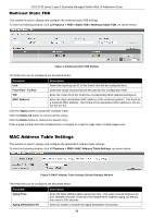
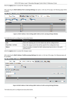
DGS-3130 Series Layer 3 Stackable Managed Switch Web UI Reference Guide Enter a page number and click the Go button to navigate to a specific page when multiple pages exist. 802.1v Protocol VLAN Protocol VLAN Profile This window is used to display and configure 802.1v protocol VLAN profiles. The 802.1v Protocol VLAN group settings support multiple VLANs for each protocol and allow the user to configure untagged ports of different protocols on the same physical port. For example, it allows the user to configure an 802.1Q and 802.1v untagged port on the same physical port. To view the following window, click L2 Features > VLAN > 802.1v Protocol VLAN > Protocol VLAN Profile, as shown below: Figure 5-10 Protocol VLAN Profile Window The fields that can be configured are described below: Parameter Profile ID Frame Type Ether Type Description Enter the 802.1v protocol VLAN profile ID here. This value must be between 1 and 16. Select the frame type option here. This function maps packets to protocoldefined VLANs by examining the type octet within the packet header to discover the type of protocol associated with it. Options to choose from are Ethernet 2, SNAP, and LLC. Enter the Ethernet type value for the group here. The protocol value is used to identify a protocol of the frame type specified. The range of values are 0x0 to 0xFFFF. Depending on the frame type, the octet string will have one of the following values: For Ethernet 2, this is a 16-bit (2-octet) hex value. For example, IPv4 is 0800, IPv6 is 86DD, ARP is 0806, etc. For IEEE802.3 SNAP, this is a 16-bit (2-octet) hex value. For IEEE802.3 LLC, this is a 2-octet IEEE 802.2 Link Service Access Point (LSAP) pair. The first octet is for Destination Service Access Point (DSAP) and the second octet is for Source. Click the Apply button to accept the changes made. Click the Delete button to remove the specific entry. Protocol VLAN Profile Interface This window is used to display and configure the protocol VLAN profile interface settings. To view the following window, click L2 Features > VLAN > 802.1v Protocol VLAN > Protocol VLAN Profile Interface, as shown below: 93
-
 1
1 -
2
-
3
-
4
-
5
-
6
-
7
-
8
-
9
-
10
-
11
-
12
-
13
-
14
-
15
-
16
-
17
-
18
-
19
-
20
-
21
-
22
-
23
-
24
-
25
-
26
-
27
-
28
-
29
-
30
-
31
-
32
-
33
-
34
-
35
-
36
-
37
-
38
-
39
-
40
-
41
-
42
-
43
-
44
-
45
-
46
-
47
-
48
-
49
-
50
-
51
-
52
-
53
-
54
-
55
-
56
-
57
-
58
-
59
-
60
-
61
-
62
-
63
-
64
-
65
-
66
-
67
-
68
-
69
-
70
-
71
-
72
-
73
-
74
-
75
-
76
-
77
-
78
-
79
-
80
-
81
-
82
-
83
-
84
-
85
-
86
-
87
-
88
-
89
-
90
-
91
-
92
-
93
-
94
-
95
-
96
-
97
-
 98
98 -
 99
99 -
 100
100 -
 101
101 -
 102
102 -
 103
103 -
 104
104 -
 105
105 -
 106
106 -
 107
107 -
 108
108 -
109
-
110
-
111
-
112
-
113
-
114
-
115
-
116
-
117
-
118
-
119
-
120
-
121
-
122
-
123
-
124
-
125
-
126
-
127
-
128
-
129
-
130
-
131
-
132
-
133
-
134
-
135
-
136
-
137
-
138
-
139
-
140
-
141
-
142
-
143
-
144
-
145
-
146
-
147
-
148
-
149
-
150
-
151
-
152
-
153
-
154
-
155
-
156
-
157
-
158
-
159
-
160
-
161
-
162
-
163
-
164
-
165
-
166
-
167
-
168
-
169
-
170
-
171
-
172
-
173
-
174
-
175
-
176
-
177
-
178
-
179
-
180
-
181
-
182
-
183
-
184
-
185
-
186
-
187
-
188
-
189
-
190
-
191
-
192
-
193
-
194
-
195
-
196
-
197
-
198
-
199
-
200
-
201
-
202
-
203
-
204
-
205
-
206
-
207
-
208
-
209
-
210
-
211
-
212
-
213
-
214
-
215
-
216
-
217
-
218
-
219
-
220
-
221
-
222
-
223
-
224
-
225
-
226
-
227
-
228
-
229
-
230
-
231
-
232
-
233
-
234
-
235
-
236
-
237
-
238
-
239
-
240
-
241
-
242
-
243
-
244
-
245
-
246
-
247
-
248
-
249
-
250
-
251
-
252
-
253
-
254
-
255
-
256
-
257
-
258
-
259
-
260
-
261
-
262
-
263
-
264
-
265
-
266
-
267
-
268
-
269
-
270
-
271
-
272
-
273
-
274
-
275
-
276
-
277
-
278
-
279
-
280
-
281
-
282
-
283
-
284
-
285
-
286
-
287
-
288
-
289
-
290
-
291
-
292
-
293
-
294
-
295
-
296
-
297
-
298
-
299
-
300
-
301
-
302
-
303
-
304
-
305
-
306
-
307
-
308
-
309
-
310
-
311
-
312
-
313
-
314
-
315
-
316
-
317
-
318
-
319
-
320
-
321
-
322
-
323
-
324
-
325
-
326
-
327
-
328
-
329
-
330
-
331
-
332
-
333
-
334
-
335
-
336
-
337
-
338
-
339
-
340
-
341
-
342
-
343
-
344
-
345
-
346
-
347
-
348
-
349
-
350
-
351
-
352
-
353
-
354
-
355
-
356
-
357
-
358
-
359
-
360
-
361
-
362
-
363
-
364
-
365
-
366
-
367
-
368
-
369
-
370
-
371
-
372
-
373
-
374
-
375
-
376
-
377
-
378
-
379
-
380
-
381
-
382
-
383
-
384
-
385
-
386
-
387
-
388
-
389
-
390
-
391
-
392
-
393
-
394
-
395
-
396
-
397
-
398
-
399
-
400
-
401
-
402
-
403
-
404
-
405
-
406
-
407
-
408
-
409
-
410
 |
 |
