D-Link DGS-3130 User Manual - Page 93
Single IP Settings
 |
View all D-Link DGS-3130 manuals
Add to My Manuals
Save this manual to your list of manuals |
Page 93 highlights
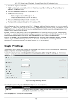
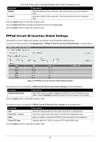
DGS-3130 Series Layer 3 Stackable Managed Switch Web UI Reference Guide Each device begins in a CaS state. A CS must change its role to CaS and then to MS, to become a MS of a SIM group. Thus, the CS cannot directly be converted to a MS. The user can manually configure a CS to become a CaS. A MS can become a CaS by: Being configured as a CaS through the CS. If report packets from the CS to the MS time out. The user can manually configure a CaS to become a CS The CaS can be configured through the CS to become a MS. After configuring one Switch to operate as the CS of a SIM group, additional Switches may join the group by manually configuring the Switch to be a MS. The CS will then serve as the in-band entry point for access to the MS. The CS's IP address will become the path to all MSs in the group and the CS's administrator password, and/or authentication will control access to all MSs in the SIM group. With SIM enabled, the applications in the CS will redirect the packets instead of executing packets. The applications will decode the packet from the administrator, modify some data, and then send it to the MS. After execution, the CS may receive a response packet from the MS, which it will encode and send it back to the administrator. When a CaS becomes a MS, it automatically becomes a member of the first SNMP community (includes read/write and read only) to which the CS belongs. However, if a MS has its own IP address, it can belong to SNMP communities to which other switches in the group, including the CS, do not belong. Single IP Settings This window is used to display and configure the SIM settings. The Switch is set as a Candidate (CaS) as the factory default configuration and Single IP Management is disabled. To view the following window, click Management > Virtual Stacking (SIM) > Single IP Settings, as shown below: Figure 4-74 Single IP Settings Window The fields that can be configured in SIM State Configure are described below: Parameter SIM State Description Select this option to enable or disable the SIM state on the Switch. Select Disabled to disable SIM on the Switch. Click the Apply button to accept the changes made. 83
-
 1
1 -
2
-
3
-
4
-
5
-
6
-
7
-
8
-
9
-
10
-
11
-
12
-
13
-
14
-
15
-
16
-
17
-
18
-
19
-
20
-
21
-
22
-
23
-
24
-
25
-
26
-
27
-
28
-
29
-
30
-
31
-
32
-
33
-
34
-
35
-
36
-
37
-
38
-
39
-
40
-
41
-
42
-
43
-
44
-
45
-
46
-
47
-
48
-
49
-
50
-
51
-
52
-
53
-
54
-
55
-
56
-
57
-
58
-
59
-
60
-
61
-
62
-
63
-
64
-
65
-
66
-
67
-
68
-
69
-
70
-
71
-
72
-
73
-
74
-
75
-
76
-
77
-
78
-
79
-
80
-
81
-
82
-
83
-
84
-
85
-
86
-
87
-
 88
88 -
 89
89 -
 90
90 -
 91
91 -
 92
92 -
 93
93 -
 94
94 -
 95
95 -
 96
96 -
 97
97 -
 98
98 -
99
-
100
-
101
-
102
-
103
-
104
-
105
-
106
-
107
-
108
-
109
-
110
-
111
-
112
-
113
-
114
-
115
-
116
-
117
-
118
-
119
-
120
-
121
-
122
-
123
-
124
-
125
-
126
-
127
-
128
-
129
-
130
-
131
-
132
-
133
-
134
-
135
-
136
-
137
-
138
-
139
-
140
-
141
-
142
-
143
-
144
-
145
-
146
-
147
-
148
-
149
-
150
-
151
-
152
-
153
-
154
-
155
-
156
-
157
-
158
-
159
-
160
-
161
-
162
-
163
-
164
-
165
-
166
-
167
-
168
-
169
-
170
-
171
-
172
-
173
-
174
-
175
-
176
-
177
-
178
-
179
-
180
-
181
-
182
-
183
-
184
-
185
-
186
-
187
-
188
-
189
-
190
-
191
-
192
-
193
-
194
-
195
-
196
-
197
-
198
-
199
-
200
-
201
-
202
-
203
-
204
-
205
-
206
-
207
-
208
-
209
-
210
-
211
-
212
-
213
-
214
-
215
-
216
-
217
-
218
-
219
-
220
-
221
-
222
-
223
-
224
-
225
-
226
-
227
-
228
-
229
-
230
-
231
-
232
-
233
-
234
-
235
-
236
-
237
-
238
-
239
-
240
-
241
-
242
-
243
-
244
-
245
-
246
-
247
-
248
-
249
-
250
-
251
-
252
-
253
-
254
-
255
-
256
-
257
-
258
-
259
-
260
-
261
-
262
-
263
-
264
-
265
-
266
-
267
-
268
-
269
-
270
-
271
-
272
-
273
-
274
-
275
-
276
-
277
-
278
-
279
-
280
-
281
-
282
-
283
-
284
-
285
-
286
-
287
-
288
-
289
-
290
-
291
-
292
-
293
-
294
-
295
-
296
-
297
-
298
-
299
-
300
-
301
-
302
-
303
-
304
-
305
-
306
-
307
-
308
-
309
-
310
-
311
-
312
-
313
-
314
-
315
-
316
-
317
-
318
-
319
-
320
-
321
-
322
-
323
-
324
-
325
-
326
-
327
-
328
-
329
-
330
-
331
-
332
-
333
-
334
-
335
-
336
-
337
-
338
-
339
-
340
-
341
-
342
-
343
-
344
-
345
-
346
-
347
-
348
-
349
-
350
-
351
-
352
-
353
-
354
-
355
-
356
-
357
-
358
-
359
-
360
-
361
-
362
-
363
-
364
-
365
-
366
-
367
-
368
-
369
-
370
-
371
-
372
-
373
-
374
-
375
-
376
-
377
-
378
-
379
-
380
-
381
-
382
-
383
-
384
-
385
-
386
-
387
-
388
-
389
-
390
-
391
-
392
-
393
-
394
-
395
-
396
-
397
-
398
-
399
-
400
-
401
-
402
-
403
-
404
-
405
-
406
-
407
-
408
-
409
-
410
 |
 |
