D-Link DGS-3130 User Manual - Page 204
VRRP Settings
 |
View all D-Link DGS-3130 manuals
Add to My Manuals
Save this manual to your list of manuals |
Page 204 highlights
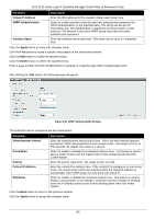
DGS-3130 Series Layer 3 Stackable Managed Switch Web UI Reference Guide VRRP Settings This window is used to display and configure the Virtual Router Redundancy Protocol (VRRP) settings. All routers in the same VRRP group must be configured with the same virtual router ID and IP address. A virtual router group is represented by a virtual router ID. The IP address of the virtual router is the default router configured on hosts. The virtual router's IP address can be a real address configured on the routers, or an unused IP address. If the virtual router address is a real IP address, the router that has this IP address is the IP address owner. A master will be elected in a group of routers that supports the same virtual routers. Others are the backup routers. The master is responsible for forwarding the packets that are sent to the virtual router. To view the following window, click L3 Features > VRRP Settings, as shown below: Figure 6-40 VRRP Settings Window The fields that can be configured in VRRP Settings are described below: Parameter SNMP Server Traps VRRP New master SNMP Server Traps VRRP Auth Fail Non-owner-ping Response Description Select to enable or disable the SNMP server traps feature for the new VRRP master. If enabled, once the device has transitioned to the master state, a trap will be sent out. Select to enable or disable the SNMP server traps feature for authentication failures. If enabled, if a packet has been received from a router whose authentication key or authentication type conflicts with this router's authentication key or authentication type, then a trap will be sent out. Select to enable or disable the non-owner ping response feature here. This feature is used to enable the virtual router in the master state to respond to ICMP echo requests for an IP address not owned but associated with this virtual router. Click the Apply button to accept the changes made. The fields that can be configured in Virtual Router Settings are described below: Parameter VLAN VRID Description Enter the VLAN interface ID used here. The range is from 1 to 4094. Enter the virtual router ID used here. This ID is used to identify the virtual router in the VRRP group. The range is from 1 to 255. 194
-
 1
1 -
2
-
3
-
4
-
5
-
6
-
7
-
8
-
9
-
10
-
11
-
12
-
13
-
14
-
15
-
16
-
17
-
18
-
19
-
20
-
21
-
22
-
23
-
24
-
25
-
26
-
27
-
28
-
29
-
30
-
31
-
32
-
33
-
34
-
35
-
36
-
37
-
38
-
39
-
40
-
41
-
42
-
43
-
44
-
45
-
46
-
47
-
48
-
49
-
50
-
51
-
52
-
53
-
54
-
55
-
56
-
57
-
58
-
59
-
60
-
61
-
62
-
63
-
64
-
65
-
66
-
67
-
68
-
69
-
70
-
71
-
72
-
73
-
74
-
75
-
76
-
77
-
78
-
79
-
80
-
81
-
82
-
83
-
84
-
85
-
86
-
87
-
88
-
89
-
90
-
91
-
92
-
93
-
94
-
95
-
96
-
97
-
98
-
99
-
100
-
101
-
102
-
103
-
104
-
105
-
106
-
107
-
108
-
109
-
110
-
111
-
112
-
113
-
114
-
115
-
116
-
117
-
118
-
119
-
120
-
121
-
122
-
123
-
124
-
125
-
126
-
127
-
128
-
129
-
130
-
131
-
132
-
133
-
134
-
135
-
136
-
137
-
138
-
139
-
140
-
141
-
142
-
143
-
144
-
145
-
146
-
147
-
148
-
149
-
150
-
151
-
152
-
153
-
154
-
155
-
156
-
157
-
158
-
159
-
160
-
161
-
162
-
163
-
164
-
165
-
166
-
167
-
168
-
169
-
170
-
171
-
172
-
173
-
174
-
175
-
176
-
177
-
178
-
179
-
180
-
181
-
182
-
183
-
184
-
185
-
186
-
187
-
188
-
189
-
190
-
191
-
192
-
193
-
194
-
195
-
196
-
197
-
198
-
 199
199 -
 200
200 -
 201
201 -
 202
202 -
 203
203 -
 204
204 -
 205
205 -
 206
206 -
 207
207 -
 208
208 -
 209
209 -
210
-
211
-
212
-
213
-
214
-
215
-
216
-
217
-
218
-
219
-
220
-
221
-
222
-
223
-
224
-
225
-
226
-
227
-
228
-
229
-
230
-
231
-
232
-
233
-
234
-
235
-
236
-
237
-
238
-
239
-
240
-
241
-
242
-
243
-
244
-
245
-
246
-
247
-
248
-
249
-
250
-
251
-
252
-
253
-
254
-
255
-
256
-
257
-
258
-
259
-
260
-
261
-
262
-
263
-
264
-
265
-
266
-
267
-
268
-
269
-
270
-
271
-
272
-
273
-
274
-
275
-
276
-
277
-
278
-
279
-
280
-
281
-
282
-
283
-
284
-
285
-
286
-
287
-
288
-
289
-
290
-
291
-
292
-
293
-
294
-
295
-
296
-
297
-
298
-
299
-
300
-
301
-
302
-
303
-
304
-
305
-
306
-
307
-
308
-
309
-
310
-
311
-
312
-
313
-
314
-
315
-
316
-
317
-
318
-
319
-
320
-
321
-
322
-
323
-
324
-
325
-
326
-
327
-
328
-
329
-
330
-
331
-
332
-
333
-
334
-
335
-
336
-
337
-
338
-
339
-
340
-
341
-
342
-
343
-
344
-
345
-
346
-
347
-
348
-
349
-
350
-
351
-
352
-
353
-
354
-
355
-
356
-
357
-
358
-
359
-
360
-
361
-
362
-
363
-
364
-
365
-
366
-
367
-
368
-
369
-
370
-
371
-
372
-
373
-
374
-
375
-
376
-
377
-
378
-
379
-
380
-
381
-
382
-
383
-
384
-
385
-
386
-
387
-
388
-
389
-
390
-
391
-
392
-
393
-
394
-
395
-
396
-
397
-
398
-
399
-
400
-
401
-
402
-
403
-
404
-
405
-
406
-
407
-
408
-
409
-
410
 |
 |
