D-Link DGS-3130 User Manual - Page 305
Web Authentication, WAC Port Settings
 |
View all D-Link DGS-3130 manuals
Add to My Manuals
Save this manual to your list of manuals |
Page 305 highlights
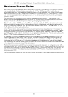
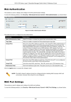
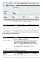
DGS-3130 Series Layer 3 Stackable Managed Switch Web UI Reference Guide Web Authentication This window is used to display and configure the Web authentication settings. To view the following window, click Security > Web-based Access Control > Web Authentication, as shown below: Figure 9-70 Web Authentication Window The fields that can be configured are described below: Parameter Web Authentication State Trap State Virtual IPv4 Virtual IPv6 Virtual URL Redirection Path Description Select to enable or disable the global Web authentication state. Select to enable or disable the Web authentication trap state. Enter the virtual IPv4 address used here. The virtual IP of Web authentication is just the characterization of the Web authentication function on the Switch. All Web authentication processes communicate with this IP address, however, the virtual IP does not respond to any ICMP packet or ARP request. So it's not allowed to configure virtual IP in the same subnet as the Switch's IP interface or the same subnet as the host PCs' subnet, otherwise the Web authentication cannot operate correctly. The defined URL only takes effect when the virtual IP address is configured. The users get the FQDN URL stored on the DNS server to get the virtual IP address. The obtained IP address must match the virtual IP address configured by the command. If the IPv4 virtual IP is not configured, the IPv4 access cannot start a Web authentication. Enter the virtual IPv6 address used here. If the IPv6 virtual IP is not configured, the IPv6 access cannot start a Web authentication. Enter the virtual URL used here. This URL can be up to 128 characters long. Enter the redirection path here. This path can be up to 128 characters long. Click the Apply button to accept the changes made. NOTE: The WAC virtual IP address should be configured before enabling WAC because WAC will not function correctly if the virtual IP is not configured. WAC Port Settings This window is used to display and configure the WAC port settings. To view the following window, click Security > Web-based Access Control > WAC Port Settings, as shown below: 295
-
 1
1 -
2
-
3
-
4
-
5
-
6
-
7
-
8
-
9
-
10
-
11
-
12
-
13
-
14
-
15
-
16
-
17
-
18
-
19
-
20
-
21
-
22
-
23
-
24
-
25
-
26
-
27
-
28
-
29
-
30
-
31
-
32
-
33
-
34
-
35
-
36
-
37
-
38
-
39
-
40
-
41
-
42
-
43
-
44
-
45
-
46
-
47
-
48
-
49
-
50
-
51
-
52
-
53
-
54
-
55
-
56
-
57
-
58
-
59
-
60
-
61
-
62
-
63
-
64
-
65
-
66
-
67
-
68
-
69
-
70
-
71
-
72
-
73
-
74
-
75
-
76
-
77
-
78
-
79
-
80
-
81
-
82
-
83
-
84
-
85
-
86
-
87
-
88
-
89
-
90
-
91
-
92
-
93
-
94
-
95
-
96
-
97
-
98
-
99
-
100
-
101
-
102
-
103
-
104
-
105
-
106
-
107
-
108
-
109
-
110
-
111
-
112
-
113
-
114
-
115
-
116
-
117
-
118
-
119
-
120
-
121
-
122
-
123
-
124
-
125
-
126
-
127
-
128
-
129
-
130
-
131
-
132
-
133
-
134
-
135
-
136
-
137
-
138
-
139
-
140
-
141
-
142
-
143
-
144
-
145
-
146
-
147
-
148
-
149
-
150
-
151
-
152
-
153
-
154
-
155
-
156
-
157
-
158
-
159
-
160
-
161
-
162
-
163
-
164
-
165
-
166
-
167
-
168
-
169
-
170
-
171
-
172
-
173
-
174
-
175
-
176
-
177
-
178
-
179
-
180
-
181
-
182
-
183
-
184
-
185
-
186
-
187
-
188
-
189
-
190
-
191
-
192
-
193
-
194
-
195
-
196
-
197
-
198
-
199
-
200
-
201
-
202
-
203
-
204
-
205
-
206
-
207
-
208
-
209
-
210
-
211
-
212
-
213
-
214
-
215
-
216
-
217
-
218
-
219
-
220
-
221
-
222
-
223
-
224
-
225
-
226
-
227
-
228
-
229
-
230
-
231
-
232
-
233
-
234
-
235
-
236
-
237
-
238
-
239
-
240
-
241
-
242
-
243
-
244
-
245
-
246
-
247
-
248
-
249
-
250
-
251
-
252
-
253
-
254
-
255
-
256
-
257
-
258
-
259
-
260
-
261
-
262
-
263
-
264
-
265
-
266
-
267
-
268
-
269
-
270
-
271
-
272
-
273
-
274
-
275
-
276
-
277
-
278
-
279
-
280
-
281
-
282
-
283
-
284
-
285
-
286
-
287
-
288
-
289
-
290
-
291
-
292
-
293
-
294
-
295
-
296
-
297
-
298
-
299
-
 300
300 -
 301
301 -
 302
302 -
 303
303 -
 304
304 -
 305
305 -
 306
306 -
 307
307 -
 308
308 -
 309
309 -
 310
310 -
311
-
312
-
313
-
314
-
315
-
316
-
317
-
318
-
319
-
320
-
321
-
322
-
323
-
324
-
325
-
326
-
327
-
328
-
329
-
330
-
331
-
332
-
333
-
334
-
335
-
336
-
337
-
338
-
339
-
340
-
341
-
342
-
343
-
344
-
345
-
346
-
347
-
348
-
349
-
350
-
351
-
352
-
353
-
354
-
355
-
356
-
357
-
358
-
359
-
360
-
361
-
362
-
363
-
364
-
365
-
366
-
367
-
368
-
369
-
370
-
371
-
372
-
373
-
374
-
375
-
376
-
377
-
378
-
379
-
380
-
381
-
382
-
383
-
384
-
385
-
386
-
387
-
388
-
389
-
390
-
391
-
392
-
393
-
394
-
395
-
396
-
397
-
398
-
399
-
400
-
401
-
402
-
403
-
404
-
405
-
406
-
407
-
408
-
409
-
410
 |
 |
