D-Link DGS-3130 User Manual - Page 293
IPv6 ND Inspection
 |
View all D-Link DGS-3130 manuals
Add to My Manuals
Save this manual to your list of manuals |
Page 293 highlights
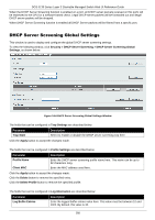
DGS-3130 Series Layer 3 Stackable Managed Switch Web UI Reference Guide Parameter VID List Description NA) is also used to detect whether a host is still reachable and determine whether to delete a binding or not. DHCP-PD snooping performs DHCPv6 snooping of Prefix Delegation (PD) to setup bindings between the Delegating Router (assigned with an IPv6 prefix) and the corresponding Requesting Router. The bindings can be used to validate the source prefix in the packets. Enter the VLAN ID list used here. Click the Apply button to accept the changes made. Click the Edit button to re-configure the specific entry. Click the Delete button to remove the specified entry. IPv6 ND Inspection This window is used to display and configure the IPv6 ND inspection settings. To view the following window, click Security > IMPB > IPv6 > IPv6 ND Inspection, as shown below: Figure 9-57 IPv6 ND Inspection Window The fields that can be configured are described below: Parameter Policy Name Device Role Validate Source-MAC Target Port Unit From Port - To Port Description Enter the policy name used here. This name can be up to 32 characters long. Select the device role here. Options to choose from are Host and Router. By default, the device's role is set as host and inspection for NS and NA messages are performed. If the device role is set as router, the NS and NA inspection is not performed. When performing NS/NA inspection, the message will be verified against the dynamic binding table learned from the ND protocol or from the DHCP. Select to enable or disable the validation of the source MAC address option here. When the Switch receives an ND message that contains a link-layer address, the source MAC address is checked against the link-layer address. The packet will be dropped if the link-layer address and the MAC addresses are different from each other. Tick this option to specify the target port. Select the Switch unit that will be used for this configuration here. Select the appropriate port range used for the configuration here. Click the Apply button to accept the changes made. Click the Edit button to re-configure the specific entry. Click the Delete button to remove the specified entry. 283
-
 1
1 -
2
-
3
-
4
-
5
-
6
-
7
-
8
-
9
-
10
-
11
-
12
-
13
-
14
-
15
-
16
-
17
-
18
-
19
-
20
-
21
-
22
-
23
-
24
-
25
-
26
-
27
-
28
-
29
-
30
-
31
-
32
-
33
-
34
-
35
-
36
-
37
-
38
-
39
-
40
-
41
-
42
-
43
-
44
-
45
-
46
-
47
-
48
-
49
-
50
-
51
-
52
-
53
-
54
-
55
-
56
-
57
-
58
-
59
-
60
-
61
-
62
-
63
-
64
-
65
-
66
-
67
-
68
-
69
-
70
-
71
-
72
-
73
-
74
-
75
-
76
-
77
-
78
-
79
-
80
-
81
-
82
-
83
-
84
-
85
-
86
-
87
-
88
-
89
-
90
-
91
-
92
-
93
-
94
-
95
-
96
-
97
-
98
-
99
-
100
-
101
-
102
-
103
-
104
-
105
-
106
-
107
-
108
-
109
-
110
-
111
-
112
-
113
-
114
-
115
-
116
-
117
-
118
-
119
-
120
-
121
-
122
-
123
-
124
-
125
-
126
-
127
-
128
-
129
-
130
-
131
-
132
-
133
-
134
-
135
-
136
-
137
-
138
-
139
-
140
-
141
-
142
-
143
-
144
-
145
-
146
-
147
-
148
-
149
-
150
-
151
-
152
-
153
-
154
-
155
-
156
-
157
-
158
-
159
-
160
-
161
-
162
-
163
-
164
-
165
-
166
-
167
-
168
-
169
-
170
-
171
-
172
-
173
-
174
-
175
-
176
-
177
-
178
-
179
-
180
-
181
-
182
-
183
-
184
-
185
-
186
-
187
-
188
-
189
-
190
-
191
-
192
-
193
-
194
-
195
-
196
-
197
-
198
-
199
-
200
-
201
-
202
-
203
-
204
-
205
-
206
-
207
-
208
-
209
-
210
-
211
-
212
-
213
-
214
-
215
-
216
-
217
-
218
-
219
-
220
-
221
-
222
-
223
-
224
-
225
-
226
-
227
-
228
-
229
-
230
-
231
-
232
-
233
-
234
-
235
-
236
-
237
-
238
-
239
-
240
-
241
-
242
-
243
-
244
-
245
-
246
-
247
-
248
-
249
-
250
-
251
-
252
-
253
-
254
-
255
-
256
-
257
-
258
-
259
-
260
-
261
-
262
-
263
-
264
-
265
-
266
-
267
-
268
-
269
-
270
-
271
-
272
-
273
-
274
-
275
-
276
-
277
-
278
-
279
-
280
-
281
-
282
-
283
-
284
-
285
-
286
-
287
-
 288
288 -
 289
289 -
 290
290 -
 291
291 -
 292
292 -
 293
293 -
 294
294 -
 295
295 -
 296
296 -
 297
297 -
 298
298 -
299
-
300
-
301
-
302
-
303
-
304
-
305
-
306
-
307
-
308
-
309
-
310
-
311
-
312
-
313
-
314
-
315
-
316
-
317
-
318
-
319
-
320
-
321
-
322
-
323
-
324
-
325
-
326
-
327
-
328
-
329
-
330
-
331
-
332
-
333
-
334
-
335
-
336
-
337
-
338
-
339
-
340
-
341
-
342
-
343
-
344
-
345
-
346
-
347
-
348
-
349
-
350
-
351
-
352
-
353
-
354
-
355
-
356
-
357
-
358
-
359
-
360
-
361
-
362
-
363
-
364
-
365
-
366
-
367
-
368
-
369
-
370
-
371
-
372
-
373
-
374
-
375
-
376
-
377
-
378
-
379
-
380
-
381
-
382
-
383
-
384
-
385
-
386
-
387
-
388
-
389
-
390
-
391
-
392
-
393
-
394
-
395
-
396
-
397
-
398
-
399
-
400
-
401
-
402
-
403
-
404
-
405
-
406
-
407
-
408
-
409
-
410
 |
 |
