D-Link DGS-3130 User Manual - Page 205
Virtual IP Address, VRRP Authentication, Interface Name, Apply, Delete, Advertisement Interval,
 |
View all D-Link DGS-3130 manuals
Add to My Manuals
Save this manual to your list of manuals |
Page 205 highlights
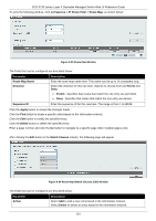
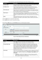
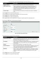
DGS-3130 Series Layer 3 Stackable Managed Switch Web UI Reference Guide Parameter Virtual IP Address VRRP Authentication Interface Name Description Enter the IPv4 address for the created virtual router group here. Select to enable and then enter the plain text authentication password for VRRP authentication on the interface here. This string can be up to 8 characters long. The authentication is applied to all virtual routers on this interface. The devices in the same VRRP group must have the same authentication password. Enter the interface name used here. This name can be up to 12 characters long. Click the Apply button to accept the changes made. Click the Find button to locate a specific entry based on the information entered. Click the Edit button to modify the specified entry. Click the Delete button to delete the specified entry. Enter a page number and click the Go button to navigate to a specific page when multiple pages exist. After clicking the Edit button, the following page will appear. Figure 6-41 VRRP Settings (Edit) Window The fields that can be configured are described below: Parameter Advertisement Interval Preemption Priority Critical IP Address Shutdown Description Enter the advertisement interval value here. This is the time interval between successive VRRP advertisements by the master router. The range is from 1 to 255 seconds. By default, this value is 1 second. Select to enable or disable the preemption feature here. This feature is used to allow a router to take over the master role if it has a better priority than the current master. Enter the priority value here. The range is from 1 to 254. Enter the critical IPv4 address here. If the critical IP is configured on one virtual router, the virtual router cannot be activated when the critical IP address is unreachable. One VRRP group can only track one critical IP. Select to enable or disable the shutdown feature here. This feature is used to disable a virtual router on an interface. Avoid the common mistake of shutting down the IP address owner router before shutting down other non-owner routers. Click the Back button to return to the previous window. Click the Apply button to accept the changes made. 195
-
 1
1 -
2
-
3
-
4
-
5
-
6
-
7
-
8
-
9
-
10
-
11
-
12
-
13
-
14
-
15
-
16
-
17
-
18
-
19
-
20
-
21
-
22
-
23
-
24
-
25
-
26
-
27
-
28
-
29
-
30
-
31
-
32
-
33
-
34
-
35
-
36
-
37
-
38
-
39
-
40
-
41
-
42
-
43
-
44
-
45
-
46
-
47
-
48
-
49
-
50
-
51
-
52
-
53
-
54
-
55
-
56
-
57
-
58
-
59
-
60
-
61
-
62
-
63
-
64
-
65
-
66
-
67
-
68
-
69
-
70
-
71
-
72
-
73
-
74
-
75
-
76
-
77
-
78
-
79
-
80
-
81
-
82
-
83
-
84
-
85
-
86
-
87
-
88
-
89
-
90
-
91
-
92
-
93
-
94
-
95
-
96
-
97
-
98
-
99
-
100
-
101
-
102
-
103
-
104
-
105
-
106
-
107
-
108
-
109
-
110
-
111
-
112
-
113
-
114
-
115
-
116
-
117
-
118
-
119
-
120
-
121
-
122
-
123
-
124
-
125
-
126
-
127
-
128
-
129
-
130
-
131
-
132
-
133
-
134
-
135
-
136
-
137
-
138
-
139
-
140
-
141
-
142
-
143
-
144
-
145
-
146
-
147
-
148
-
149
-
150
-
151
-
152
-
153
-
154
-
155
-
156
-
157
-
158
-
159
-
160
-
161
-
162
-
163
-
164
-
165
-
166
-
167
-
168
-
169
-
170
-
171
-
172
-
173
-
174
-
175
-
176
-
177
-
178
-
179
-
180
-
181
-
182
-
183
-
184
-
185
-
186
-
187
-
188
-
189
-
190
-
191
-
192
-
193
-
194
-
195
-
196
-
197
-
198
-
199
-
 200
200 -
 201
201 -
 202
202 -
 203
203 -
 204
204 -
 205
205 -
 206
206 -
 207
207 -
 208
208 -
 209
209 -
 210
210 -
211
-
212
-
213
-
214
-
215
-
216
-
217
-
218
-
219
-
220
-
221
-
222
-
223
-
224
-
225
-
226
-
227
-
228
-
229
-
230
-
231
-
232
-
233
-
234
-
235
-
236
-
237
-
238
-
239
-
240
-
241
-
242
-
243
-
244
-
245
-
246
-
247
-
248
-
249
-
250
-
251
-
252
-
253
-
254
-
255
-
256
-
257
-
258
-
259
-
260
-
261
-
262
-
263
-
264
-
265
-
266
-
267
-
268
-
269
-
270
-
271
-
272
-
273
-
274
-
275
-
276
-
277
-
278
-
279
-
280
-
281
-
282
-
283
-
284
-
285
-
286
-
287
-
288
-
289
-
290
-
291
-
292
-
293
-
294
-
295
-
296
-
297
-
298
-
299
-
300
-
301
-
302
-
303
-
304
-
305
-
306
-
307
-
308
-
309
-
310
-
311
-
312
-
313
-
314
-
315
-
316
-
317
-
318
-
319
-
320
-
321
-
322
-
323
-
324
-
325
-
326
-
327
-
328
-
329
-
330
-
331
-
332
-
333
-
334
-
335
-
336
-
337
-
338
-
339
-
340
-
341
-
342
-
343
-
344
-
345
-
346
-
347
-
348
-
349
-
350
-
351
-
352
-
353
-
354
-
355
-
356
-
357
-
358
-
359
-
360
-
361
-
362
-
363
-
364
-
365
-
366
-
367
-
368
-
369
-
370
-
371
-
372
-
373
-
374
-
375
-
376
-
377
-
378
-
379
-
380
-
381
-
382
-
383
-
384
-
385
-
386
-
387
-
388
-
389
-
390
-
391
-
392
-
393
-
394
-
395
-
396
-
397
-
398
-
399
-
400
-
401
-
402
-
403
-
404
-
405
-
406
-
407
-
408
-
409
-
410
 |
 |
