Dell PowerEdge 2970 Hardware Owner's Manual - Page 109
Control Panel Assembly (Service-only Procedure), Removing the Control Panel Assembly
 |
View all Dell PowerEdge 2970 manuals
Add to My Manuals
Save this manual to your list of manuals |
Page 109 highlights
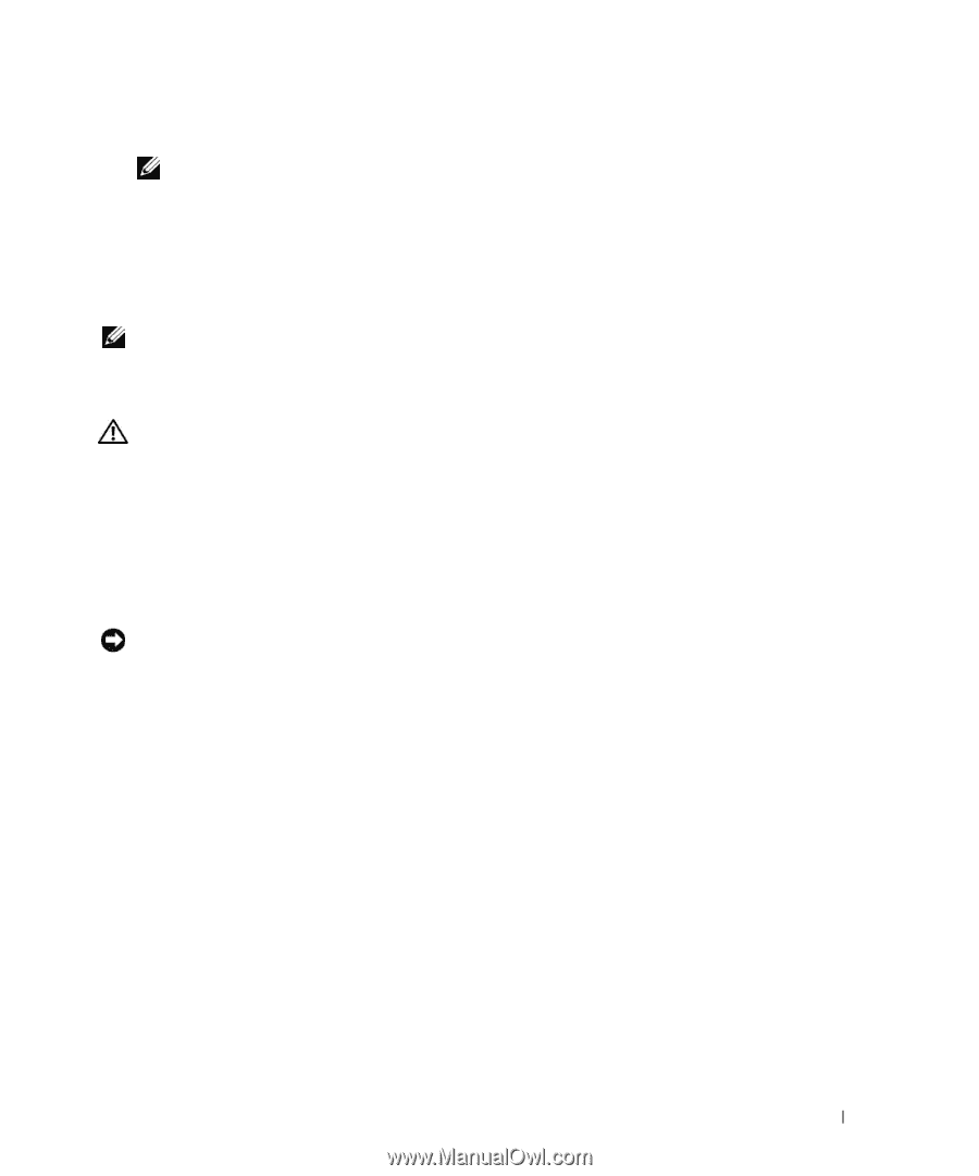
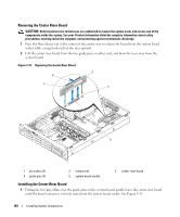
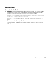
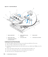
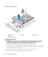
6 Reinstall the hard drives. See "Installing a Hot-Plug Hard Drive" on page 58. NOTE: Reinstall the hard drives in the same drive bays from which they were removed. 7 If applicable, reconnect the optical drive power cable to the backplane board. See "Installing the Optical Drive" on page 83. 8 Close the system. See "Closing the System" on page 56. Control Panel Assembly (Service-only Procedure) NOTE: The control panel assembly consists of two separate modules-the display module and the control panel circuit board. Use the following instructions to remove and install either module. Removing the Control Panel Assembly CAUTION: Only trained service technicians are authorized to remove the system cover and access any of the components inside the system. See your Product Information Guide for complete information about safety precautions, working inside the computer, and protecting against electrostatic discharge. 1 If applicable, remove the bezel. See "Removing the Front Bezel" on page 54. 2 Turn off the system and attached peripherals, and disconnect the system from the electrical outlet and peripherals. 3 Open the system. See "Opening the System" on page 55. 4 Disconnect the control panel cable at back of the control panel board. See Figure 3-34. NOTICE: Do not pull on the cable to unseat the connector. Doing so can damage the cable. a Squeeze the metal tabs on the ends of the cable connector. b Gently work the connector out of the socket. 5 Disconnect the display module cable from the control panel board. See Figure 3-34. 6 Remove the three screws that secure the control panel board to the system chassis and remove the board. See Figure 3-34. 7 Remove the display module: a Insert the end of paper clip into the hole on the right side of the display module and gently pry off the label. b Using a T10 Torx driver, remove the two screws that secure the display module to the system chassis. c Remove the display module from the chassis cutout. Installing System Components 109
-
 1
1 -
2
-
3
-
4
-
5
-
6
-
7
-
8
-
9
-
10
-
11
-
12
-
13
-
14
-
15
-
16
-
17
-
18
-
19
-
20
-
21
-
22
-
23
-
24
-
25
-
26
-
27
-
28
-
29
-
30
-
31
-
32
-
33
-
34
-
35
-
36
-
37
-
38
-
39
-
40
-
41
-
42
-
43
-
44
-
45
-
46
-
47
-
48
-
49
-
50
-
51
-
52
-
53
-
54
-
55
-
56
-
57
-
58
-
59
-
60
-
61
-
62
-
63
-
64
-
65
-
66
-
67
-
68
-
69
-
70
-
71
-
72
-
73
-
74
-
75
-
76
-
77
-
78
-
79
-
80
-
81
-
82
-
83
-
84
-
85
-
86
-
87
-
88
-
89
-
90
-
91
-
92
-
93
-
94
-
95
-
96
-
97
-
98
-
99
-
100
-
101
-
102
-
103
-
 104
104 -
 105
105 -
 106
106 -
 107
107 -
 108
108 -
 109
109 -
 110
110 -
 111
111 -
 112
112 -
 113
113 -
 114
114 -
115
-
116
-
117
-
118
-
119
-
120
-
121
-
122
-
123
-
124
-
125
-
126
-
127
-
128
-
129
-
130
-
131
-
132
-
133
-
134
-
135
-
136
-
137
-
138
-
139
-
140
-
141
-
142
-
143
-
144
-
145
-
146
-
147
-
148
-
149
-
150
-
151
-
152
-
153
-
154
-
155
-
156
-
157
-
158
-
159
-
160
-
161
-
162
-
163
-
164
-
165
-
166
-
167
-
168
-
169
-
170
-
171
-
172
-
173
-
174
-
175
-
176
-
177
-
178
-
179
-
180
-
181
-
182
-
183
-
184
-
185
-
186
-
187
-
188
 |
 |