Dell PowerEdge 2970 Hardware Owner's Manual - Page 74
Removing an Expansion Card, Cooling Shroud, Removing the Cooling Shroud
 |
View all Dell PowerEdge 2970 manuals
Add to My Manuals
Save this manual to your list of manuals |
Page 74 highlights
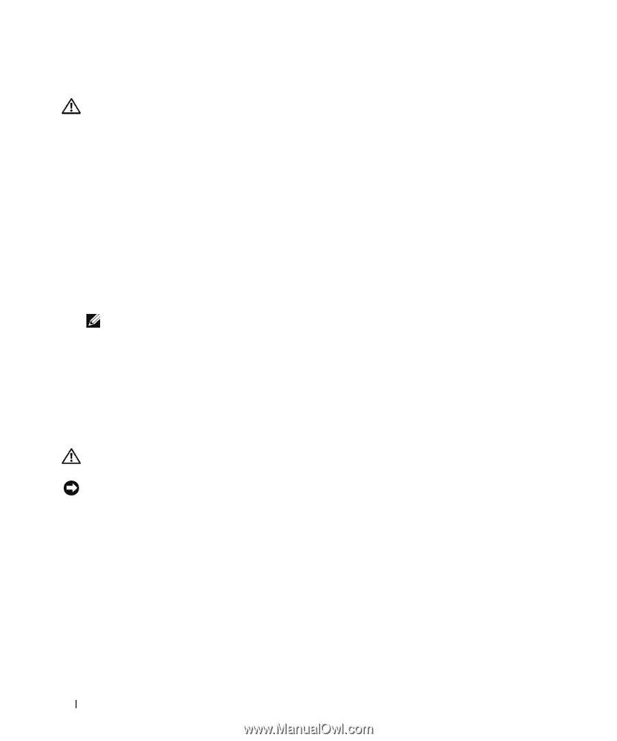
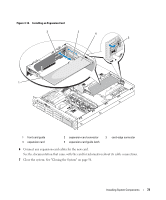
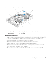
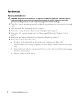
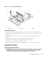
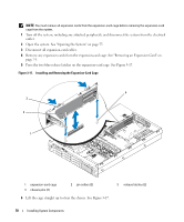
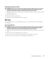
Removing an Expansion Card CAUTION: Only trained service technicians are authorized to remove the system cover and access any of the components inside the system. See your Product Information Guide for complete information about safety precautions, working inside the computer, and protecting against electrostatic discharge. 1 Turn off the system, including any attached peripherals, and disconnect the system from the electrical outlet. 2 Open the system. See "Opening the System" on page 55. 3 Disconnect all expansion-card cables. 4 Release the expansion card: a Open the expansion-card latch. See Figure 3-14. b Grasp the expansion card by its top corners, and carefully remove it from the expansion-card connector. 5 If you are removing the card permanently, install a metal filler bracket over the empty expansion slot opening and close the expansion-card latch. NOTE: You must install a filler bracket over an empty expansion slot to maintain Federal Communications Commission (FCC) certification of the system. The brackets also aid in proper cooling and airflow inside the system. 6 Reconnect all expansion-card cables. 7 Close the system. See "Closing the System" on page 56. Cooling Shroud The cooling shroud produces and directs airflow over the system processor(s) and memory modules. CAUTION: The DIMMs are hot to the touch for some time after the system has been powered down. Allow the DIMMs to cool before handling them. NOTICE: Never operate your system with the memory cooling shroud removed. Overheating of the system can develop quickly resulting in a shutdown of the system and the loss of data. Removing the Cooling Shroud 1 Turn off the system, including any attached peripherals, and disconnect the system from the electrical outlet. 2 Open the system. See "Opening the System" on page 55. 3 Remove the optical drive cable from the cable tabs on top of the cooling shroud. 4 Remove the expansion cards from the left expansion-card riser board. 5 Remove the left riser board. "Removing the Left Expansion-Card Riser Board" on page 102 6 Rotate the shroud upward and toward the front of the system on its hinges, and then lift the shroud out of the system. See Figure 3-15. 74 Installing System Components
-
 1
1 -
2
-
3
-
4
-
5
-
6
-
7
-
8
-
9
-
10
-
11
-
12
-
13
-
14
-
15
-
16
-
17
-
18
-
19
-
20
-
21
-
22
-
23
-
24
-
25
-
26
-
27
-
28
-
29
-
30
-
31
-
32
-
33
-
34
-
35
-
36
-
37
-
38
-
39
-
40
-
41
-
42
-
43
-
44
-
45
-
46
-
47
-
48
-
49
-
50
-
51
-
52
-
53
-
54
-
55
-
56
-
57
-
58
-
59
-
60
-
61
-
62
-
63
-
64
-
65
-
66
-
67
-
68
-
 69
69 -
 70
70 -
 71
71 -
 72
72 -
 73
73 -
 74
74 -
 75
75 -
 76
76 -
 77
77 -
 78
78 -
 79
79 -
80
-
81
-
82
-
83
-
84
-
85
-
86
-
87
-
88
-
89
-
90
-
91
-
92
-
93
-
94
-
95
-
96
-
97
-
98
-
99
-
100
-
101
-
102
-
103
-
104
-
105
-
106
-
107
-
108
-
109
-
110
-
111
-
112
-
113
-
114
-
115
-
116
-
117
-
118
-
119
-
120
-
121
-
122
-
123
-
124
-
125
-
126
-
127
-
128
-
129
-
130
-
131
-
132
-
133
-
134
-
135
-
136
-
137
-
138
-
139
-
140
-
141
-
142
-
143
-
144
-
145
-
146
-
147
-
148
-
149
-
150
-
151
-
152
-
153
-
154
-
155
-
156
-
157
-
158
-
159
-
160
-
161
-
162
-
163
-
164
-
165
-
166
-
167
-
168
-
169
-
170
-
171
-
172
-
173
-
174
-
175
-
176
-
177
-
178
-
179
-
180
-
181
-
182
-
183
-
184
-
185
-
186
-
187
-
188
 |
 |