Dell PowerEdge 2970 Hardware Owner's Manual - Page 14
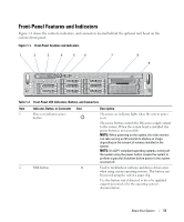
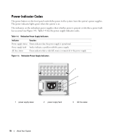
Table 1-2., Front-Panel LED Indicators, Buttons, and Connectors, Indicator, Description - error codes
 |
View all Dell PowerEdge 2970 manuals
Add to My Manuals
Save this manual to your list of manuals |
Page 14 highlights
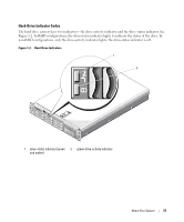
Table 1-2. Front-Panel LED Indicators, Buttons, and Connectors (continued) Item Indicator, Button, or Connector Icon 3 System identification button 4 LCD panel 5 USB connectors (2) Description The identification buttons on the front and back panels can be used to locate a particular system within a rack. When one of these buttons is pushed, the LCD panel on the front and the blue system status indicator on the back blink until one of the buttons is pushed again. Provides system ID, status information, and system error messages. The LCD lights during normal system operation. Both the systems management software and the identification buttons located on the front and back of the system can cause the LCD to flash blue to identify a particular system. The LCD lights amber when the system needs attention, and the LCD panel displays an error code followed by descriptive text. NOTE: If the system is connected to AC power and an error has been detected, the LCD lights amber regardless of whether the system has been powered on. Connects USB devices to the system. The ports are USB 2.0-complaint. 6 Video connector Connects a monitor to the system. 7 Hard drives (8) 8 Optical drive (optional) 9 Media bay Eight 2.5-inch hot plug One optional slimline CD, DVD, or CD-RW/DVD drive. NOTE: DVD devices are data only. Bay for optional diskette drive and/or tape drive. 14 About Your System
-
 1
1 -
2
-
3
-
4
-
5
-
6
-
7
-
8
-
 9
9 -
 10
10 -
 11
11 -
 12
12 -
 13
13 -
 14
14 -
 15
15 -
 16
16 -
 17
17 -
 18
18 -
 19
19 -
20
-
21
-
22
-
23
-
24
-
25
-
26
-
27
-
28
-
29
-
30
-
31
-
32
-
33
-
34
-
35
-
36
-
37
-
38
-
39
-
40
-
41
-
42
-
43
-
44
-
45
-
46
-
47
-
48
-
49
-
50
-
51
-
52
-
53
-
54
-
55
-
56
-
57
-
58
-
59
-
60
-
61
-
62
-
63
-
64
-
65
-
66
-
67
-
68
-
69
-
70
-
71
-
72
-
73
-
74
-
75
-
76
-
77
-
78
-
79
-
80
-
81
-
82
-
83
-
84
-
85
-
86
-
87
-
88
-
89
-
90
-
91
-
92
-
93
-
94
-
95
-
96
-
97
-
98
-
99
-
100
-
101
-
102
-
103
-
104
-
105
-
106
-
107
-
108
-
109
-
110
-
111
-
112
-
113
-
114
-
115
-
116
-
117
-
118
-
119
-
120
-
121
-
122
-
123
-
124
-
125
-
126
-
127
-
128
-
129
-
130
-
131
-
132
-
133
-
134
-
135
-
136
-
137
-
138
-
139
-
140
-
141
-
142
-
143
-
144
-
145
-
146
-
147
-
148
-
149
-
150
-
151
-
152
-
153
-
154
-
155
-
156
-
157
-
158
-
159
-
160
-
161
-
162
-
163
-
164
-
165
-
166
-
167
-
168
-
169
-
170
-
171
-
172
-
173
-
174
-
175
-
176
-
177
-
178
-
179
-
180
-
181
-
182
-
183
-
184
-
185
-
186
-
187
-
188
 |
 |