Dell PowerEdge 2970 Hardware Owner's Manual - Page 84
Installing an Optical Drive Into the Optical Drive Tray, Diskette Drive
 |
View all Dell PowerEdge 2970 manuals
Add to My Manuals
Save this manual to your list of manuals |
Page 84 highlights
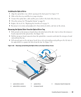
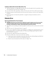
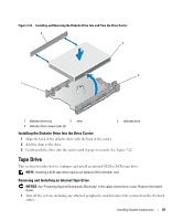
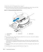
Installing an Optical Drive Into the Optical Drive Tray 1 With the optical drive at a slight angle to the drive tray, lower the right side of the optical drive down onto the right side of the drive tray. See Figure 3-20. 2 Lower the left side of the optical drive and press the drive down into the tray until it snaps into place. 3 Rotate the interposer board toward the tray and connector the interposer connector to the optical drive connector. 4 Push the interposer in towards the optical drive to engage the interposer board release tab. See Figure 3-20. Diskette Drive Removing the Diskette Drive From the System CAUTION: Only trained service technicians are authorized to remove the system cover and access any of the components inside the system. See your Product Information Guide for complete information about safety precautions, working inside the computer, and protecting against electrostatic discharge. 1 Turn off the system, including any attached peripherals, and disconnect the system from the electrical outlet. 2 Open the system. See "Opening the System" on page 55. 3 If your system configuration includes a tape backup device installed in the optional media bay, remove the tape backup device's strain relief bracket. See "Removing and Replacing the Tape Drive Cable Retention Bracket" on page 89. 4 Disconnect the cable from the back of the diskette drive. 5 Release the diskette drive carrier from its slot in the media bay: a Gently squeeze down on the plastic tabs on the side of the carrier while pushing toward the front of the system until you feel the carrier sliding freely forward. b Slide the carrier forward and out of the chassis. See Figure 3-22. 84 Installing System Components
-
 1
1 -
2
-
3
-
4
-
5
-
6
-
7
-
8
-
9
-
10
-
11
-
12
-
13
-
14
-
15
-
16
-
17
-
18
-
19
-
20
-
21
-
22
-
23
-
24
-
25
-
26
-
27
-
28
-
29
-
30
-
31
-
32
-
33
-
34
-
35
-
36
-
37
-
38
-
39
-
40
-
41
-
42
-
43
-
44
-
45
-
46
-
47
-
48
-
49
-
50
-
51
-
52
-
53
-
54
-
55
-
56
-
57
-
58
-
59
-
60
-
61
-
62
-
63
-
64
-
65
-
66
-
67
-
68
-
69
-
70
-
71
-
72
-
73
-
74
-
75
-
76
-
77
-
78
-
 79
79 -
 80
80 -
 81
81 -
 82
82 -
 83
83 -
 84
84 -
 85
85 -
 86
86 -
 87
87 -
 88
88 -
 89
89 -
90
-
91
-
92
-
93
-
94
-
95
-
96
-
97
-
98
-
99
-
100
-
101
-
102
-
103
-
104
-
105
-
106
-
107
-
108
-
109
-
110
-
111
-
112
-
113
-
114
-
115
-
116
-
117
-
118
-
119
-
120
-
121
-
122
-
123
-
124
-
125
-
126
-
127
-
128
-
129
-
130
-
131
-
132
-
133
-
134
-
135
-
136
-
137
-
138
-
139
-
140
-
141
-
142
-
143
-
144
-
145
-
146
-
147
-
148
-
149
-
150
-
151
-
152
-
153
-
154
-
155
-
156
-
157
-
158
-
159
-
160
-
161
-
162
-
163
-
164
-
165
-
166
-
167
-
168
-
169
-
170
-
171
-
172
-
173
-
174
-
175
-
176
-
177
-
178
-
179
-
180
-
181
-
182
-
183
-
184
-
185
-
186
-
187
-
188
 |
 |