Dell PowerEdge 2970 Hardware Owner's Manual - Page 94
Installing Memory Modules, CAUTION, NOTICE
 |
View all Dell PowerEdge 2970 manuals
Add to My Manuals
Save this manual to your list of manuals |
Page 94 highlights
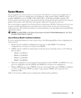
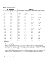
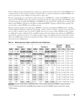
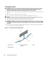
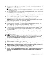
Installing Memory Modules CAUTION: Only trained service technicians are authorized to remove the system cover and access any of the components inside the system. See your Product Information Guide for complete information about safety precautions, working inside the computer, and protecting against electrostatic discharge. 1 Turn off the system, including any attached peripherals, and disconnect the system from the electrical outlet. 2 Open the system. See "Opening the System" on page 55. 3 Remove the memory cooling shroud. See "Removing the Cooling Shroud" on page 74. NOTICE: Never remove the memory cooling shroud without first powering down the system. Overheating of the system can develop quickly resulting in a shutdown of the system and the loss of data. 4 Locate the memory module sockets on the system board. See Figure 6-2. CAUTION: The DIMMs are hot to the touch for some time after the system has been powered down. Allow time for the DIMMs to cool before handling them. Handle the DIMMs by the card edges and avoid touching the DIMM components. 5 Press the ejectors on the memory module socket down and out, as shown in Figure 3-26, to allow the memory module to be inserted into the socket. Figure 3-26. Installing and Removing a Memory Module 1 2 4 3 1 memory module 4 alignment keys (2) 2 memory module socket ejectors (2) 3 socket 94 Installing System Components
-
 1
1 -
2
-
3
-
4
-
5
-
6
-
7
-
8
-
9
-
10
-
11
-
12
-
13
-
14
-
15
-
16
-
17
-
18
-
19
-
20
-
21
-
22
-
23
-
24
-
25
-
26
-
27
-
28
-
29
-
30
-
31
-
32
-
33
-
34
-
35
-
36
-
37
-
38
-
39
-
40
-
41
-
42
-
43
-
44
-
45
-
46
-
47
-
48
-
49
-
50
-
51
-
52
-
53
-
54
-
55
-
56
-
57
-
58
-
59
-
60
-
61
-
62
-
63
-
64
-
65
-
66
-
67
-
68
-
69
-
70
-
71
-
72
-
73
-
74
-
75
-
76
-
77
-
78
-
79
-
80
-
81
-
82
-
83
-
84
-
85
-
86
-
87
-
88
-
 89
89 -
 90
90 -
 91
91 -
 92
92 -
 93
93 -
 94
94 -
 95
95 -
 96
96 -
 97
97 -
 98
98 -
 99
99 -
100
-
101
-
102
-
103
-
104
-
105
-
106
-
107
-
108
-
109
-
110
-
111
-
112
-
113
-
114
-
115
-
116
-
117
-
118
-
119
-
120
-
121
-
122
-
123
-
124
-
125
-
126
-
127
-
128
-
129
-
130
-
131
-
132
-
133
-
134
-
135
-
136
-
137
-
138
-
139
-
140
-
141
-
142
-
143
-
144
-
145
-
146
-
147
-
148
-
149
-
150
-
151
-
152
-
153
-
154
-
155
-
156
-
157
-
158
-
159
-
160
-
161
-
162
-
163
-
164
-
165
-
166
-
167
-
168
-
169
-
170
-
171
-
172
-
173
-
174
-
175
-
176
-
177
-
178
-
179
-
180
-
181
-
182
-
183
-
184
-
185
-
186
-
187
-
188
 |
 |