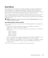
Dell PowerEdge 2970 Hardware Owner's Manual - Page 89
for the connector location., Reconnect the system to its electrical outlet and turn the system
 |
View all Dell PowerEdge 2970 manuals
Add to My Manuals
Save this manual to your list of manuals |
Page 89 highlights
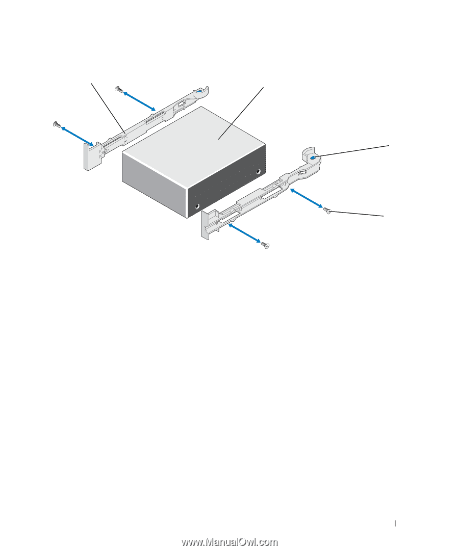
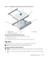
Figure 3-24. Removing and Installing an Internal Tape Drive 1 2 3 4 1 tape drive rails (2) 4 screws (4) 2 tape drive 3 rail release tabs (2) 8 Route the tape drive's interface cable through the tape drive cable retention bracket. See Figure 3-25. 9 Connect the tape drive interface cable to the drive controller connector: • For a SCSI tape drive, connect the cable to the port on the SCSI controller card in the expansion slot. • For a SATA tape drive, connect to either the SATA_A or SATA_B on-board SATA ports. See Figure 6-2 for the connector locations on the system board. 10 Connect the tape drive power cable to the tape drive power connector on the backplane. See Figure 6-3 for the connector location. 11 Reconnect the system to its electrical outlet and turn the system on, including any attached peripherals. 12 Perform a tape backup and verification test with the drive as instructed in the software documentation that came with the drive. Removing and Replacing the Tape Drive Cable Retention Bracket The optional SCSI tape drive connects to the system board through an expansion card plugged into one of the PCIe expansion card slots. The SCSI tape drive cable is routed along the right side of the chassis and behind the tape drive cable retention bracket. Installing System Components 89
-
 1
1 -
2
-
3
-
4
-
5
-
6
-
7
-
8
-
9
-
10
-
11
-
12
-
13
-
14
-
15
-
16
-
17
-
18
-
19
-
20
-
21
-
22
-
23
-
24
-
25
-
26
-
27
-
28
-
29
-
30
-
31
-
32
-
33
-
34
-
35
-
36
-
37
-
38
-
39
-
40
-
41
-
42
-
43
-
44
-
45
-
46
-
47
-
48
-
49
-
50
-
51
-
52
-
53
-
54
-
55
-
56
-
57
-
58
-
59
-
60
-
61
-
62
-
63
-
64
-
65
-
66
-
67
-
68
-
69
-
70
-
71
-
72
-
73
-
74
-
75
-
76
-
77
-
78
-
79
-
80
-
81
-
82
-
83
-
 84
84 -
 85
85 -
 86
86 -
 87
87 -
 88
88 -
 89
89 -
 90
90 -
 91
91 -
 92
92 -
 93
93 -
 94
94 -
95
-
96
-
97
-
98
-
99
-
100
-
101
-
102
-
103
-
104
-
105
-
106
-
107
-
108
-
109
-
110
-
111
-
112
-
113
-
114
-
115
-
116
-
117
-
118
-
119
-
120
-
121
-
122
-
123
-
124
-
125
-
126
-
127
-
128
-
129
-
130
-
131
-
132
-
133
-
134
-
135
-
136
-
137
-
138
-
139
-
140
-
141
-
142
-
143
-
144
-
145
-
146
-
147
-
148
-
149
-
150
-
151
-
152
-
153
-
154
-
155
-
156
-
157
-
158
-
159
-
160
-
161
-
162
-
163
-
164
-
165
-
166
-
167
-
168
-
169
-
170
-
171
-
172
-
173
-
174
-
175
-
176
-
177
-
178
-
179
-
180
-
181
-
182
-
183
-
184
-
185
-
186
-
187
-
188
 |
 |