Dell PowerEdge 2970 Hardware Owner's Manual - Page 92
Memory Sparing Support, screen of the System Setup program. See Using the System Setup Program - node interleave
 |
View all Dell PowerEdge 2970 manuals
Add to My Manuals
Save this manual to your list of manuals |
Page 92 highlights
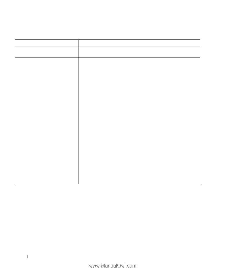
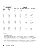
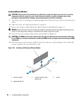
Table 3-1. Memory Configurations Total System Memory Single-Processor Dual-Processor System System 1 GB 2 GB 2 GB 4 GB 2 GB 4 GB 3 GB 6 GB 4 GB 8 GB 4 GB 8 GB 5 GB 10 GB 6 GB 12 GB 8 GB 16 GB 8 GB 16 GB 9 GB 18 GB 10 GB 20 GB 12 GB 24 GB 16 GB 32 GB 16 GB 32 GB 18 GB 36 GB 20 GB 40 GB 24 GB 48 GB 32 GB 64 GB * When available. DIMM Socket DIMM 1 / DIMM 5 DIMM 2/ DIMM 6 DIMM 3/ DIMM 7 DIMM 4/ DIMM 8 512 MB 512 MB 1 GB 1 GB 1 GB 2 GB 2 GB 2 GB 2 GB 4 GB 4 GB 4 GB 4 GB 4 GB 8 GB* 8 GB* 8 GB* 8 GB* 8 GB* 512 MB 512 MB 1 GB 1 GB 1 GB 2 GB 2 GB 2 GB 2 GB 4 GB 4 GB 4 GB 4 GB 4 GB 8 GB* 8 GB* 8 GB* 8 GB* 8 GB* 512 MB 512 MB 1 GB 512 MB 1 GB 2 GB 512 MB 1 GB 2 GB 4 GB 1 GB 2 GB 4 GB 8 GB* 512 MB 512 MB 1 GB 512 MB 1 GB 2 GB 512 MB 1 GB 2 GB 4 GB 1 GB 2 GB 4 GB 8 GB* Memory Sparing Support Memory sparing is supported in single- or dual-processor systems that have one of the fully populated memory configurations shown in Table 3-1. The memory sparing feature must be enabled in the Memory Information screen of the System Setup program. See "Using the System Setup Program" on page 37. To use memory sparing, you must disable node interleaving. Memory sparing is applied independently to the two groups of DIMMs on opposite sides of the processor sockets. To support memory sparing, all DIMM sockets within a DIMM group must be populated. 92 Installing System Components
-
 1
1 -
2
-
3
-
4
-
5
-
6
-
7
-
8
-
9
-
10
-
11
-
12
-
13
-
14
-
15
-
16
-
17
-
18
-
19
-
20
-
21
-
22
-
23
-
24
-
25
-
26
-
27
-
28
-
29
-
30
-
31
-
32
-
33
-
34
-
35
-
36
-
37
-
38
-
39
-
40
-
41
-
42
-
43
-
44
-
45
-
46
-
47
-
48
-
49
-
50
-
51
-
52
-
53
-
54
-
55
-
56
-
57
-
58
-
59
-
60
-
61
-
62
-
63
-
64
-
65
-
66
-
67
-
68
-
69
-
70
-
71
-
72
-
73
-
74
-
75
-
76
-
77
-
78
-
79
-
80
-
81
-
82
-
83
-
84
-
85
-
86
-
 87
87 -
 88
88 -
 89
89 -
 90
90 -
 91
91 -
 92
92 -
 93
93 -
 94
94 -
 95
95 -
 96
96 -
 97
97 -
98
-
99
-
100
-
101
-
102
-
103
-
104
-
105
-
106
-
107
-
108
-
109
-
110
-
111
-
112
-
113
-
114
-
115
-
116
-
117
-
118
-
119
-
120
-
121
-
122
-
123
-
124
-
125
-
126
-
127
-
128
-
129
-
130
-
131
-
132
-
133
-
134
-
135
-
136
-
137
-
138
-
139
-
140
-
141
-
142
-
143
-
144
-
145
-
146
-
147
-
148
-
149
-
150
-
151
-
152
-
153
-
154
-
155
-
156
-
157
-
158
-
159
-
160
-
161
-
162
-
163
-
164
-
165
-
166
-
167
-
168
-
169
-
170
-
171
-
172
-
173
-
174
-
175
-
176
-
177
-
178
-
179
-
180
-
181
-
182
-
183
-
184
-
185
-
186
-
187
-
188
 |
 |