Dell PowerEdge 2970 Hardware Owner's Manual - Page 88
and controller card, if applicable, and compare the jumper and switch settings with those in the drive
 |
View all Dell PowerEdge 2970 manuals
Add to My Manuals
Save this manual to your list of manuals |
Page 88 highlights
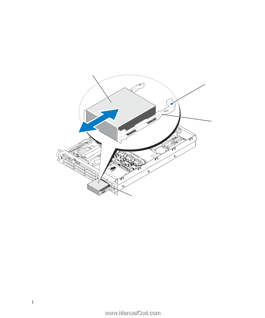
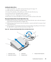
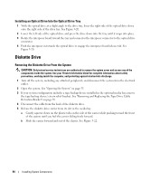
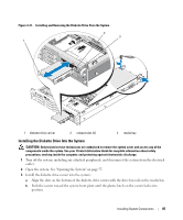
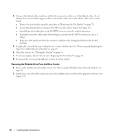
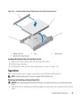
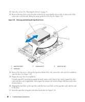
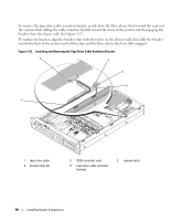
2 Open the system. See "Opening the System" on page 55. 3 Remove the tape drive carrier from the media bay by squeezing the release tabs on either side of the carrier down and forward, sliding the carrier gently from the bay. See Figure 3-23. Figure 3-23. Removing and Installing the Tape Drive Carrier 1 2 3 1 tape drive blank 4 media bay 4 2 release tab (2) 3 tape drive rails 4 Remove the four screws affixing the tape drive blank to the rails, and set the rails aside for installation onto the drive. See Figure 3-24. 5 Prepare the tape drive for installation. Ground yourself by touching an unpainted metal surface on the back of the system, unpack the drive (and controller card, if applicable), and compare the jumper and switch settings with those in the drive documentation. 6 Aligning the four holes on the tape drive with the four screw holes on the tape drive rails, affix the rails to the drive. 7 Insert the tape drive along the rails in the media bay. See Figure 3-24. 88 Installing System Components
-
 1
1 -
2
-
3
-
4
-
5
-
6
-
7
-
8
-
9
-
10
-
11
-
12
-
13
-
14
-
15
-
16
-
17
-
18
-
19
-
20
-
21
-
22
-
23
-
24
-
25
-
26
-
27
-
28
-
29
-
30
-
31
-
32
-
33
-
34
-
35
-
36
-
37
-
38
-
39
-
40
-
41
-
42
-
43
-
44
-
45
-
46
-
47
-
48
-
49
-
50
-
51
-
52
-
53
-
54
-
55
-
56
-
57
-
58
-
59
-
60
-
61
-
62
-
63
-
64
-
65
-
66
-
67
-
68
-
69
-
70
-
71
-
72
-
73
-
74
-
75
-
76
-
77
-
78
-
79
-
80
-
81
-
82
-
 83
83 -
 84
84 -
 85
85 -
 86
86 -
 87
87 -
 88
88 -
 89
89 -
 90
90 -
 91
91 -
 92
92 -
 93
93 -
94
-
95
-
96
-
97
-
98
-
99
-
100
-
101
-
102
-
103
-
104
-
105
-
106
-
107
-
108
-
109
-
110
-
111
-
112
-
113
-
114
-
115
-
116
-
117
-
118
-
119
-
120
-
121
-
122
-
123
-
124
-
125
-
126
-
127
-
128
-
129
-
130
-
131
-
132
-
133
-
134
-
135
-
136
-
137
-
138
-
139
-
140
-
141
-
142
-
143
-
144
-
145
-
146
-
147
-
148
-
149
-
150
-
151
-
152
-
153
-
154
-
155
-
156
-
157
-
158
-
159
-
160
-
161
-
162
-
163
-
164
-
165
-
166
-
167
-
168
-
169
-
170
-
171
-
172
-
173
-
174
-
175
-
176
-
177
-
178
-
179
-
180
-
181
-
182
-
183
-
184
-
185
-
186
-
187
-
188
 |
 |