Dell PowerEdge 2970 Hardware Owner's Manual - Page 53
Front Bezel, During an installation or troubleshooting procedure - optical drive install
 |
View all Dell PowerEdge 2970 manuals
Add to My Manuals
Save this manual to your list of manuals |
Page 53 highlights
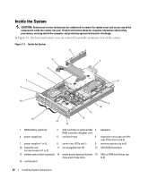
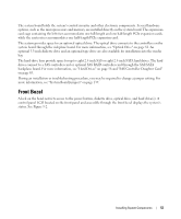
The system board holds the system's control circuitry and other electronic components. Several hardware options, such as the microprocessors and memory, are installed directly on the system board. The expansioncard cage containing the left riser accommodates one full-length and one half-length PCIe expansion cards, while the center riser accommodates one half-length PCIe expansion card. The system provides space for an optional optical drive. The optical drive connects to the controllers on the system board through the sideplane board. For more information, see "Optical Drive" on page 81. An optional 3.5-inch diskette drive and an optional tape drive are also available for installation into the media bay. The hard-drive bays provide space for up to eight 2.5-inch SAS or eight 2.5-inch SATA hard drives. The hard drives connect to a SAS controller card or optional SAS RAID controller card through the SAS/SATA backplane board. For more information, see "Hard Drives" on page 56 and "SAS Controller Daughter Card" on page 65. During an installation or troubleshooting procedure, you may be required to change a jumper setting. For more information, see "System Board Jumpers" on page 139. Front Bezel A lock on the bezel restricts access to the power button, diskette drive, optical drive, and hard drive(s). A control panel LCD located on the front panel and accessible through the front bezel displays the system's status. See Figure 3-2. Installing System Components 53
-
 1
1 -
2
-
3
-
4
-
5
-
6
-
7
-
8
-
9
-
10
-
11
-
12
-
13
-
14
-
15
-
16
-
17
-
18
-
19
-
20
-
21
-
22
-
23
-
24
-
25
-
26
-
27
-
28
-
29
-
30
-
31
-
32
-
33
-
34
-
35
-
36
-
37
-
38
-
39
-
40
-
41
-
42
-
43
-
44
-
45
-
46
-
47
-
 48
48 -
 49
49 -
 50
50 -
 51
51 -
 52
52 -
 53
53 -
 54
54 -
 55
55 -
 56
56 -
 57
57 -
 58
58 -
59
-
60
-
61
-
62
-
63
-
64
-
65
-
66
-
67
-
68
-
69
-
70
-
71
-
72
-
73
-
74
-
75
-
76
-
77
-
78
-
79
-
80
-
81
-
82
-
83
-
84
-
85
-
86
-
87
-
88
-
89
-
90
-
91
-
92
-
93
-
94
-
95
-
96
-
97
-
98
-
99
-
100
-
101
-
102
-
103
-
104
-
105
-
106
-
107
-
108
-
109
-
110
-
111
-
112
-
113
-
114
-
115
-
116
-
117
-
118
-
119
-
120
-
121
-
122
-
123
-
124
-
125
-
126
-
127
-
128
-
129
-
130
-
131
-
132
-
133
-
134
-
135
-
136
-
137
-
138
-
139
-
140
-
141
-
142
-
143
-
144
-
145
-
146
-
147
-
148
-
149
-
150
-
151
-
152
-
153
-
154
-
155
-
156
-
157
-
158
-
159
-
160
-
161
-
162
-
163
-
164
-
165
-
166
-
167
-
168
-
169
-
170
-
171
-
172
-
173
-
174
-
175
-
176
-
177
-
178
-
179
-
180
-
181
-
182
-
183
-
184
-
185
-
186
-
187
-
188
 |
 |