Dell PowerEdge 2970 Hardware Owner's Manual - Page 142
Table 6-2., System Board Connectors, Connector, Description, TCP/IP Offload Engine Key
 |
View all Dell PowerEdge 2970 manuals
Add to My Manuals
Save this manual to your list of manuals |
Page 142 highlights
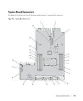
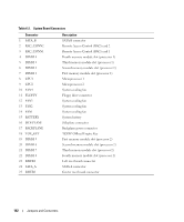
Table 6-2. System Board Connectors Connector 1 SATA_B 2 RAC_CONN2 3 RAC_CONN1 4 DIMM 4 5 DIMM 3 6 DIMM 2 7 DIMM 1 8 CPU1 9 CPU2 10 FAN4 11 FLOPPY 12 FAN3 13 FAN2 14 FAN1 15 BATTERY 16 SIDEPLANE 17 BACKPLANE 18 TOE_KEY 19 DIMM 5 20 DIMM 6 21 DIMM 7 22 DIMM 8 23 RISER1 24 SATA_A 25 RISER2 Description SATA B connector Remote Access Control (RAC) card 2 Remote Access Control (RAC) card 1 Fourth memory module slot (processor 1) Third memory module slot (processor 1) Second memory module slot (processor 1) First memory module slot (processor 1) Microprocessor 1 Microprocessor 2 System cooling fan Floppy drive connector System cooling fan System cooling fan System cooling fan System battery Sideplane connector Backplane power connector TCP/IP Offload Engine Key First memory module slot (processor 2) Second memory module slot (processor 2) Third memory module slot (processor 2) Fourth memory module slot (processor 2) Left riser board connector SATA A connector Center riser board connector 142 Jumpers and Connectors
-
 1
1 -
2
-
3
-
4
-
5
-
6
-
7
-
8
-
9
-
10
-
11
-
12
-
13
-
14
-
15
-
16
-
17
-
18
-
19
-
20
-
21
-
22
-
23
-
24
-
25
-
26
-
27
-
28
-
29
-
30
-
31
-
32
-
33
-
34
-
35
-
36
-
37
-
38
-
39
-
40
-
41
-
42
-
43
-
44
-
45
-
46
-
47
-
48
-
49
-
50
-
51
-
52
-
53
-
54
-
55
-
56
-
57
-
58
-
59
-
60
-
61
-
62
-
63
-
64
-
65
-
66
-
67
-
68
-
69
-
70
-
71
-
72
-
73
-
74
-
75
-
76
-
77
-
78
-
79
-
80
-
81
-
82
-
83
-
84
-
85
-
86
-
87
-
88
-
89
-
90
-
91
-
92
-
93
-
94
-
95
-
96
-
97
-
98
-
99
-
100
-
101
-
102
-
103
-
104
-
105
-
106
-
107
-
108
-
109
-
110
-
111
-
112
-
113
-
114
-
115
-
116
-
117
-
118
-
119
-
120
-
121
-
122
-
123
-
124
-
125
-
126
-
127
-
128
-
129
-
130
-
131
-
132
-
133
-
134
-
135
-
136
-
 137
137 -
 138
138 -
 139
139 -
 140
140 -
 141
141 -
 142
142 -
 143
143 -
 144
144 -
 145
145 -
 146
146 -
 147
147 -
148
-
149
-
150
-
151
-
152
-
153
-
154
-
155
-
156
-
157
-
158
-
159
-
160
-
161
-
162
-
163
-
164
-
165
-
166
-
167
-
168
-
169
-
170
-
171
-
172
-
173
-
174
-
175
-
176
-
177
-
178
-
179
-
180
-
181
-
182
-
183
-
184
-
185
-
186
-
187
-
188
 |
 |