Dell PowerEdge 2970 Hardware Owner's Manual - Page 70
Removing a RAID Battery, Configuring the Boot Device, Internal USB Memory Key Connector - boot from usb
 |
View all Dell PowerEdge 2970 manuals
Add to My Manuals
Save this manual to your list of manuals |
Page 70 highlights
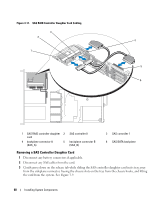
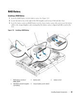
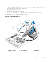
Removing a RAID Battery 1 Disconnect the cable between the RAID battery and the SAS RAID controller daughter card. See Figure 3-12. 2 Press down and to the left on the battery carrier to disengage the carrier from the chassis battery carrier slots. 3 Gently pulling back the two guides holding the RAID battery into the battery carrier, draw out the RAID battery from the battery carrier. Configuring the Boot Device NOTE: System boot is not supported from an external device attached to a SAS or SCSI adapter. See support.dell.com for the latest support information about booting from external devices. If you plan to boot the system from a hard drive, the drive must be attached to the primary (or boot) controller. The device that the system boots from is determined by the boot order specified in the System Setup program. The System Setup program provides options that the system uses to scan for installed boot devices. See "Using the System Setup Program" on page 37 for information about the System Setup program. Internal USB Memory Key Connector The system provides an internal USB connector located on the sideplane board for use with the optional bootable USB flash memory key (see Figure 6-4). To boot from the USB memory key, you must specify the USB device in the boot sequence in the System Setup program. See "System Setup Options" on page 38. For information on creating a bootable file on the USB memory key, see the user documentation that accompanied the USB memory key. Installing the Optional Internal USB Memory Key CAUTION: Only trained service technicians are authorized to remove the system cover and access any of the components inside the system. See your Product Information Guide for complete information about safety precautions, working inside the computer, and protecting against electrostatic discharge. 1 Turn off the system, including any attached peripherals, and disconnect the system from its electrical outlet. 2 Open the system. See "Opening the System" on page 55. 3 Remove the SAS controller card. See "Removing a SAS Controller Daughter Card" on page 68. 4 If present, disconnect the optical drive cable from the sideplane board. NOTE: You do not need to disconnect the control panel cable from the sideplane to complete the memory key installation. 5 Press inward on the sideplane release tabs, lift the sideplane up enough to clear the system board pins, and rotate the end of the sideplane upward. See Figure 3-32. 70 Installing System Components
-
 1
1 -
2
-
3
-
4
-
5
-
6
-
7
-
8
-
9
-
10
-
11
-
12
-
13
-
14
-
15
-
16
-
17
-
18
-
19
-
20
-
21
-
22
-
23
-
24
-
25
-
26
-
27
-
28
-
29
-
30
-
31
-
32
-
33
-
34
-
35
-
36
-
37
-
38
-
39
-
40
-
41
-
42
-
43
-
44
-
45
-
46
-
47
-
48
-
49
-
50
-
51
-
52
-
53
-
54
-
55
-
56
-
57
-
58
-
59
-
60
-
61
-
62
-
63
-
64
-
 65
65 -
 66
66 -
 67
67 -
 68
68 -
 69
69 -
 70
70 -
 71
71 -
 72
72 -
 73
73 -
 74
74 -
 75
75 -
76
-
77
-
78
-
79
-
80
-
81
-
82
-
83
-
84
-
85
-
86
-
87
-
88
-
89
-
90
-
91
-
92
-
93
-
94
-
95
-
96
-
97
-
98
-
99
-
100
-
101
-
102
-
103
-
104
-
105
-
106
-
107
-
108
-
109
-
110
-
111
-
112
-
113
-
114
-
115
-
116
-
117
-
118
-
119
-
120
-
121
-
122
-
123
-
124
-
125
-
126
-
127
-
128
-
129
-
130
-
131
-
132
-
133
-
134
-
135
-
136
-
137
-
138
-
139
-
140
-
141
-
142
-
143
-
144
-
145
-
146
-
147
-
148
-
149
-
150
-
151
-
152
-
153
-
154
-
155
-
156
-
157
-
158
-
159
-
160
-
161
-
162
-
163
-
164
-
165
-
166
-
167
-
168
-
169
-
170
-
171
-
172
-
173
-
174
-
175
-
176
-
177
-
178
-
179
-
180
-
181
-
182
-
183
-
184
-
185
-
186
-
187
-
188
 |
 |