Dell PowerEdge 2970 Hardware Owner's Manual - Page 96
Integrated NIC TOE, Processors, Removing a Processor
 |
View all Dell PowerEdge 2970 manuals
Add to My Manuals
Save this manual to your list of manuals |
Page 96 highlights
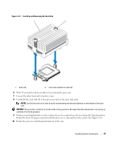
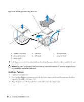
5 Press down and out on the ejectors on each end of the socket until the memory module pops out of the socket. See Figure 3-26. 6 Replace the memory cooling shroud. See "Installing the Cooling Shroud" on page 75. NOTICE: Never operate your system with the memory cooling shroud removed. Overheating of the system can develop quickly resulting in a shutdown of the system and the loss of data. 7 Close the system. See "Closing the System" on page 56. Integrated NIC TOE The TCP/IP Offload Engine (TOE) functionality of the system's integrated NIC is activated by the TOE NIC hardware key installed in the TOE_KEY socket on the system board (see Figure 6-2.) See the user documentation that came with the hardware key for information on how to set up and configure the TOE feature. Processors You can upgrade your processor(s) to take advantage of future options in speed and functionality. Each processor and its associated internal cache memory are contained in a land grid array (LGA) package that is installed in a ZIF socket on the system board. Removing a Processor CAUTION: Only trained service technicians are authorized to remove the system cover and access any of the components inside the system. See your Product Information Guide for complete information about safety precautions, working inside the computer, and protecting against electrostatic discharge. 1 Prior to upgrading your system, download the latest system BIOS version on support.dell.com. 2 Turn off the system, including any attached peripherals, and disconnect the system from the electrical outlet. 3 Open the system. See "Opening the System" on page 55. 4 Remove the cooling shroud. See "Removing the Cooling Shroud" on page 74. NOTICE: When you remove the heat sink, the possibility exists that the processor might adhere to the heat sink and be removed from the socket. It is recommended that you remove the heat sink while the processor is still warm. NOTICE: Never remove the heat sink from a processor unless you intend to remove the processor. The heat sink is necessary to maintain proper thermal conditions. 5 Using a #2 Phillips screwdriver, loosen one of the two heat-sink retention screws. See Figure 3-27. 96 Installing System Components
-
 1
1 -
2
-
3
-
4
-
5
-
6
-
7
-
8
-
9
-
10
-
11
-
12
-
13
-
14
-
15
-
16
-
17
-
18
-
19
-
20
-
21
-
22
-
23
-
24
-
25
-
26
-
27
-
28
-
29
-
30
-
31
-
32
-
33
-
34
-
35
-
36
-
37
-
38
-
39
-
40
-
41
-
42
-
43
-
44
-
45
-
46
-
47
-
48
-
49
-
50
-
51
-
52
-
53
-
54
-
55
-
56
-
57
-
58
-
59
-
60
-
61
-
62
-
63
-
64
-
65
-
66
-
67
-
68
-
69
-
70
-
71
-
72
-
73
-
74
-
75
-
76
-
77
-
78
-
79
-
80
-
81
-
82
-
83
-
84
-
85
-
86
-
87
-
88
-
89
-
90
-
 91
91 -
 92
92 -
 93
93 -
 94
94 -
 95
95 -
 96
96 -
 97
97 -
 98
98 -
 99
99 -
 100
100 -
 101
101 -
102
-
103
-
104
-
105
-
106
-
107
-
108
-
109
-
110
-
111
-
112
-
113
-
114
-
115
-
116
-
117
-
118
-
119
-
120
-
121
-
122
-
123
-
124
-
125
-
126
-
127
-
128
-
129
-
130
-
131
-
132
-
133
-
134
-
135
-
136
-
137
-
138
-
139
-
140
-
141
-
142
-
143
-
144
-
145
-
146
-
147
-
148
-
149
-
150
-
151
-
152
-
153
-
154
-
155
-
156
-
157
-
158
-
159
-
160
-
161
-
162
-
163
-
164
-
165
-
166
-
167
-
168
-
169
-
170
-
171
-
172
-
173
-
174
-
175
-
176
-
177
-
178
-
179
-
180
-
181
-
182
-
183
-
184
-
185
-
186
-
187
-
188
 |
 |