Dell PowerEdge 2970 Hardware Owner's Manual - Page 111
System Board (Service-only Procedure), Removing the System Board
 |
View all Dell PowerEdge 2970 manuals
Add to My Manuals
Save this manual to your list of manuals |
Page 111 highlights
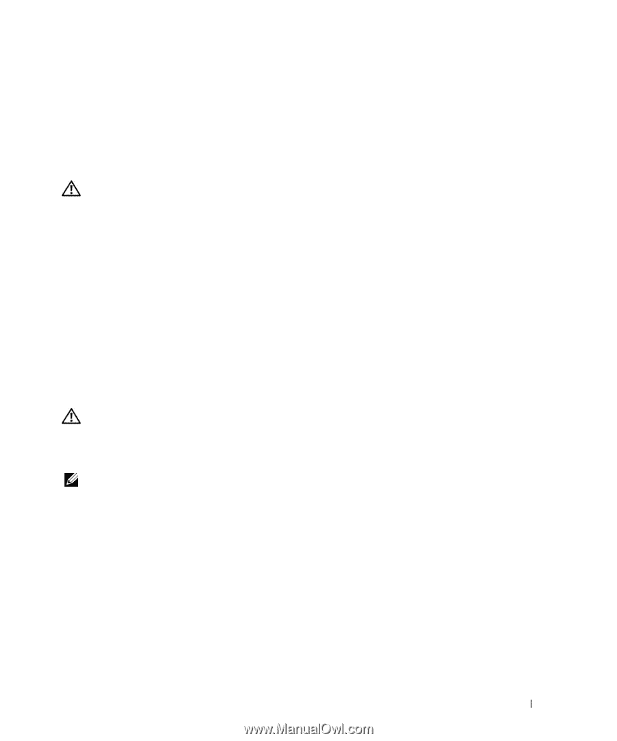
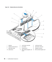
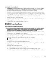
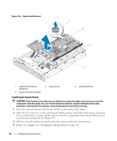
7 Reconnect the system to the power source and turn on the system and attached peripherals. 8 If applicable, install the bezel. System Board (Service-only Procedure) Removing the System Board CAUTION: Only trained service technicians are authorized to remove the system cover and access any of the components inside the system. See your Product Information Guide for complete information about safety precautions, working inside the computer, and protecting against electrostatic discharge. 1 Turn off the system and attached peripherals, and disconnect the system from the electrical outlet. 2 Open the system. See "Opening the System" on page 55. 3 If applicable, remove any expansion cards. See "Removing an Expansion Card" on page 74. 4 Remove the power supplies. See "Removing a Power Supply" on page 61. 5 Remove the expansion-card cage. See "Removing the Expansion-Card Cage" on page 77. 6 Remove the center riser board. See "Removing the Center Riser Board" on page 104. 7 Remove the cooling shroud. See "Removing the Cooling Shroud" on page 74. 8 Remove the fans. See "Removing a System Fan" on page 63. 9 Remove the fan bracket. See "Removing the Fan Bracket" on page 76. 10 If applicable, remove the RAC card. See "Removing the RAC Card" on page 79. CAUTION: The DIMMs are hot to the touch for some time after the system has been powered down. Allow time for the DIMMs to cool before handling them. Handle the DIMMs by the card edges and avoid touching the DIMM components. 11 Remove the memory modules. See "Removing Memory Modules" on page 95. NOTE: While removing the memory modules, record the memory module socket locations to ensure proper installation. 12 Remove the heatsink(s) and microprocessor(s). See "Removing a Processor" on page 96. 13 Remove the TOE key, if present. See Figure 6-2 for the location of the TOE key. 14 Remove the sideplane. See "Removing the Sideplane Board" on page 105. 15 Remove the system board: a Pull the system-board tray riser release pin. See Figure 3-35. b While pulling the release pin, slide the system-board tray toward the front of the chassis. c Lift up the system-board tray and remove it from the chassis. Installing System Components 111
-
 1
1 -
2
-
3
-
4
-
5
-
6
-
7
-
8
-
9
-
10
-
11
-
12
-
13
-
14
-
15
-
16
-
17
-
18
-
19
-
20
-
21
-
22
-
23
-
24
-
25
-
26
-
27
-
28
-
29
-
30
-
31
-
32
-
33
-
34
-
35
-
36
-
37
-
38
-
39
-
40
-
41
-
42
-
43
-
44
-
45
-
46
-
47
-
48
-
49
-
50
-
51
-
52
-
53
-
54
-
55
-
56
-
57
-
58
-
59
-
60
-
61
-
62
-
63
-
64
-
65
-
66
-
67
-
68
-
69
-
70
-
71
-
72
-
73
-
74
-
75
-
76
-
77
-
78
-
79
-
80
-
81
-
82
-
83
-
84
-
85
-
86
-
87
-
88
-
89
-
90
-
91
-
92
-
93
-
94
-
95
-
96
-
97
-
98
-
99
-
100
-
101
-
102
-
103
-
104
-
105
-
 106
106 -
 107
107 -
 108
108 -
 109
109 -
 110
110 -
 111
111 -
 112
112 -
 113
113 -
 114
114 -
 115
115 -
 116
116 -
117
-
118
-
119
-
120
-
121
-
122
-
123
-
124
-
125
-
126
-
127
-
128
-
129
-
130
-
131
-
132
-
133
-
134
-
135
-
136
-
137
-
138
-
139
-
140
-
141
-
142
-
143
-
144
-
145
-
146
-
147
-
148
-
149
-
150
-
151
-
152
-
153
-
154
-
155
-
156
-
157
-
158
-
159
-
160
-
161
-
162
-
163
-
164
-
165
-
166
-
167
-
168
-
169
-
170
-
171
-
172
-
173
-
174
-
175
-
176
-
177
-
178
-
179
-
180
-
181
-
182
-
183
-
184
-
185
-
186
-
187
-
188
 |
 |