Dell PowerEdge 2970 Hardware Owner's Manual - Page 56
Closing the System, Hard Drives
 |
View all Dell PowerEdge 2970 manuals
Add to My Manuals
Save this manual to your list of manuals |
Page 56 highlights
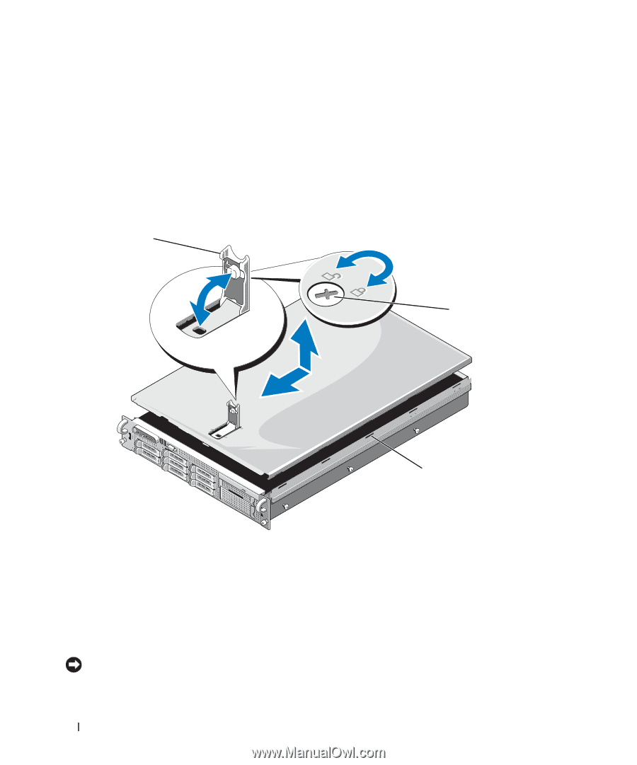
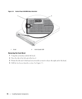
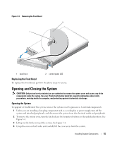
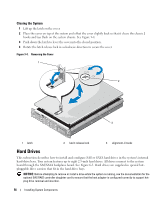
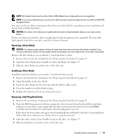
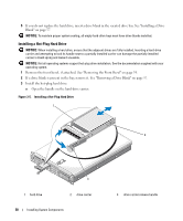
Closing the System 1 Lift up the latch on the cover. 2 Place the cover on top of the system and offset the cover slightly back so that it clears the chassis J hooks and lays flush on the system chassis. See Figure 3-4. 3 Push down the latch to lever the cover into the closed position. 4 Rotate the latch release lock in a clockwise direction to secure the cover. Figure 3-4. Removing the Cover 1 2 3 1 latch 2 latch release lock 3 alignment J hooks Hard Drives This subsection describes how to install and configure SAS or SATA hard drives in the system's internal hard-drive bays. Your system features up to eight 2.5-inch hard drives. All drives connect to the system board through the SAS/SATA backplane board. See Figure 6-3. Hard drives are supplied in special hotpluggable drive carriers that fit in the hard-drive bays. NOTICE: Before attempting to remove or install a drive while the system is running, see the documentation for the optional SAS RAID controller daughter card to ensure that the host adapter is configured correctly to support hotplug drive removal and insertion. 56 Installing System Components
-
 1
1 -
2
-
3
-
4
-
5
-
6
-
7
-
8
-
9
-
10
-
11
-
12
-
13
-
14
-
15
-
16
-
17
-
18
-
19
-
20
-
21
-
22
-
23
-
24
-
25
-
26
-
27
-
28
-
29
-
30
-
31
-
32
-
33
-
34
-
35
-
36
-
37
-
38
-
39
-
40
-
41
-
42
-
43
-
44
-
45
-
46
-
47
-
48
-
49
-
50
-
 51
51 -
 52
52 -
 53
53 -
 54
54 -
 55
55 -
 56
56 -
 57
57 -
 58
58 -
 59
59 -
 60
60 -
 61
61 -
62
-
63
-
64
-
65
-
66
-
67
-
68
-
69
-
70
-
71
-
72
-
73
-
74
-
75
-
76
-
77
-
78
-
79
-
80
-
81
-
82
-
83
-
84
-
85
-
86
-
87
-
88
-
89
-
90
-
91
-
92
-
93
-
94
-
95
-
96
-
97
-
98
-
99
-
100
-
101
-
102
-
103
-
104
-
105
-
106
-
107
-
108
-
109
-
110
-
111
-
112
-
113
-
114
-
115
-
116
-
117
-
118
-
119
-
120
-
121
-
122
-
123
-
124
-
125
-
126
-
127
-
128
-
129
-
130
-
131
-
132
-
133
-
134
-
135
-
136
-
137
-
138
-
139
-
140
-
141
-
142
-
143
-
144
-
145
-
146
-
147
-
148
-
149
-
150
-
151
-
152
-
153
-
154
-
155
-
156
-
157
-
158
-
159
-
160
-
161
-
162
-
163
-
164
-
165
-
166
-
167
-
168
-
169
-
170
-
171
-
172
-
173
-
174
-
175
-
176
-
177
-
178
-
179
-
180
-
181
-
182
-
183
-
184
-
185
-
186
-
187
-
188
 |
 |