HP 9000 rp4410-4 User Service Guide, Fifth Edition - HP 9000 rp4410/4440 - Page 101
Replacing the Removed Modules, Installing the SCSI Cable B to the SCSI Adapter Board
 |
View all HP 9000 rp4410-4 manuals
Add to My Manuals
Save this manual to your list of manuals |
Page 101 highlights
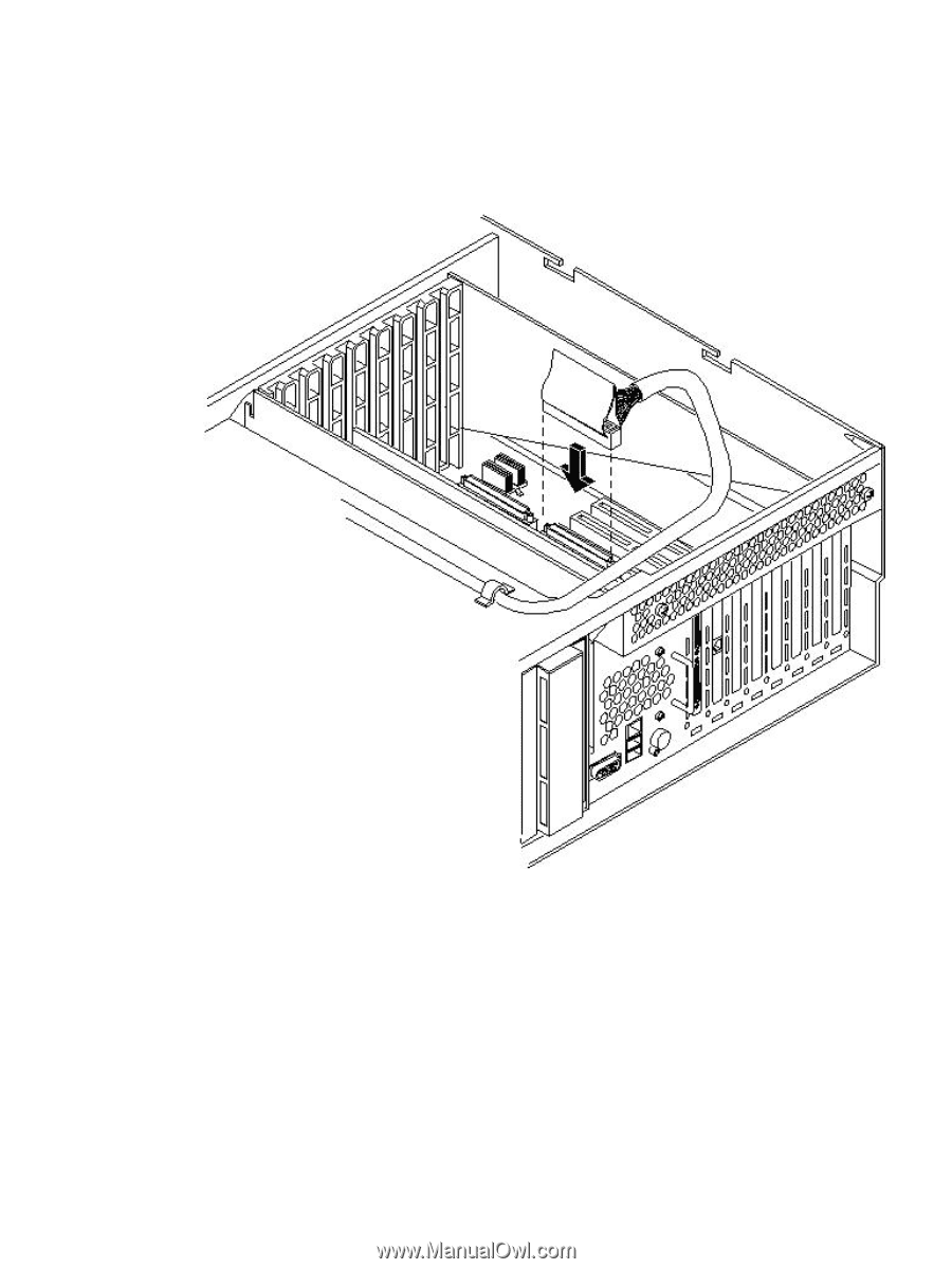
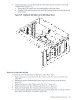
5. Connect the other end of the SCSI Cable B to the SCSI B channel connector on the SCSI adapter board. (Figure 3-39) a. Release the SCSI Cable B from its stowed position within the chassis. b. Plug the SCSI Cable B connector into the SCSI B channel connector located at the rear of the board. Figure 3-39 Installing the SCSI Cable B to the SCSI Adapter Board Replacing the Removed Modules To return the server to operational configuration, follow these steps: 1. Replace the processor extender board. (See "Replacing the Processor Extender Board" (page 84).) 2. Replace the memory extender board. (See "Replacing the Memory Extender Board" (page 88).) 3. Replace the top cover. (See "Replacing the Top Cover" (page 66).) 4. Replace the front cover. (See "Replacing the Front Cover" (page 65).) 5. Replace the front bezel. (See "Replacing the Front Bezel" (page 64).) 6. If rack-mounted, slide the server back into the rack until it stops. (See "Installing the Server Into a Rack, Non-HP Rack, or Pedestal" (page 102).) Installing Additional Components 101
-
 1
1 -
2
-
3
-
4
-
5
-
6
-
7
-
8
-
9
-
10
-
11
-
12
-
13
-
14
-
15
-
16
-
17
-
18
-
19
-
20
-
21
-
22
-
23
-
24
-
25
-
26
-
27
-
28
-
29
-
30
-
31
-
32
-
33
-
34
-
35
-
36
-
37
-
38
-
39
-
40
-
41
-
42
-
43
-
44
-
45
-
46
-
47
-
48
-
49
-
50
-
51
-
52
-
53
-
54
-
55
-
56
-
57
-
58
-
59
-
60
-
61
-
62
-
63
-
64
-
65
-
66
-
67
-
68
-
69
-
70
-
71
-
72
-
73
-
74
-
75
-
76
-
77
-
78
-
79
-
80
-
81
-
82
-
83
-
84
-
85
-
86
-
87
-
88
-
89
-
90
-
91
-
92
-
93
-
94
-
95
-
 96
96 -
 97
97 -
 98
98 -
 99
99 -
 100
100 -
 101
101 -
 102
102 -
 103
103 -
 104
104 -
 105
105 -
 106
106 -
107
-
108
-
109
-
110
-
111
-
112
-
113
-
114
-
115
-
116
-
117
-
118
-
119
-
120
-
121
-
122
-
123
-
124
-
125
-
126
-
127
-
128
-
129
-
130
-
131
-
132
-
133
-
134
-
135
-
136
-
137
-
138
-
139
-
140
-
141
-
142
-
143
-
144
-
145
-
146
-
147
-
148
-
149
-
150
-
151
-
152
-
153
-
154
-
155
-
156
-
157
-
158
-
159
-
160
-
161
-
162
-
163
-
164
-
165
-
166
-
167
-
168
-
169
-
170
-
171
-
172
-
173
-
174
-
175
-
176
-
177
-
178
-
179
-
180
-
181
-
182
-
183
-
184
-
185
-
186
-
187
-
188
-
189
-
190
-
191
-
192
-
193
-
194
-
195
-
196
-
197
-
198
-
199
-
200
-
201
-
202
-
203
-
204
-
205
-
206
-
207
-
208
-
209
-
210
-
211
-
212
-
213
-
214
-
215
-
216
-
217
-
218
-
219
-
220
-
221
-
222
-
223
-
224
-
225
-
226
-
227
-
228
-
229
-
230
-
231
-
232
-
233
-
234
-
235
-
236
-
237
-
238
-
239
-
240
-
241
-
242
-
243
-
244
-
245
-
246
 |
 |