HP 9000 rp4410-4 User Service Guide, Fifth Edition - HP 9000 rp4410/4440 - Page 216
Midplane Riser Board, Removing the Midplane Riser Board
 |
View all HP 9000 rp4410-4 manuals
Add to My Manuals
Save this manual to your list of manuals |
Page 216 highlights
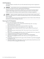
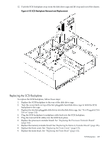
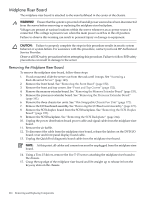
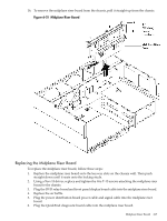
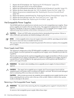
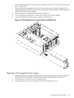
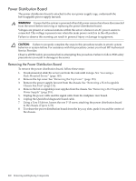
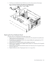
Midplane Riser Board The midplane riser board is attached to the main bulkhead in the center of the chassis. WARNING! Ensure that the system is powered off and all power sources have been disconnected from the server before removing or replacing the midplane riser backplane. Voltages are present at various locations within the server whenever an ac power source is connected. This voltage is present even when the main power switch is in the off position. Failure to observe this warning can result in personal injury or damage to equipment. CAUTION: Failure to properly complete the steps in this procedure results in erratic system behavior or system failure. For assistance with this procedure, contact your local HP Authorized Service Provider. Observe all ESD safety precautions before attempting this procedure. Failure to follow ESD safety precautions can result in damage to the server. Removing the Midplane Riser Board To remove the midplane riser board, follow these steps: 1. If rack-mounted, slide the server out from the rack until it stops. See "Accessing a Rack-Mounted Server" (page 149). 2. Remove the front bezel. See "Removing the Front Bezel" (page 152). 3. Remove the front and top covers. See "Front and Top Covers" (page 152). 4. Remove the memory extender board. See "Removing the Memory Extender Board" (page 155). 5. Remove the processor extender board. See "Removing the Processor Extender Board" (page 161). 6. Remove the three chassis fan units. See "Hot-Swappable Chassis Fan Unit" (page 172). 7. Remove the I/O baseboard assembly. See "Removing the I/O Baseboard Assembly" (page 175). 8. Remove the SCSI duplex board from the SCSI backplane. See "Removing the SCSI Duplex Board" (page 195). 9. Remove the SCSI backplane. See "Removing the SCSI Backplane" (page 214). 10. Unplug the power distribution board power cable and signal cable from the midplane riser board. 11. Remove the air baffle. 12. To disconnect the cable from the midplane riser board, release the latches on the DVD I/O board cover and front panel display board cable. 13. Unplug the QuickFind diagnostic board cable from the midplane riser board. NOTE: At this point, all cables and connectors must be unplugged from the midplane riser board. 14. Using a Torx 15 driver, remove the five T-15 screws attaching the midplane riser board to the chassis. 15. Grasp the top edge of the midplane riser board and lift straight up to release it from the keyway slots on the chassis. 216 Removing and Replacing Components
-
 1
1 -
2
-
3
-
4
-
5
-
6
-
7
-
8
-
9
-
10
-
11
-
12
-
13
-
14
-
15
-
16
-
17
-
18
-
19
-
20
-
21
-
22
-
23
-
24
-
25
-
26
-
27
-
28
-
29
-
30
-
31
-
32
-
33
-
34
-
35
-
36
-
37
-
38
-
39
-
40
-
41
-
42
-
43
-
44
-
45
-
46
-
47
-
48
-
49
-
50
-
51
-
52
-
53
-
54
-
55
-
56
-
57
-
58
-
59
-
60
-
61
-
62
-
63
-
64
-
65
-
66
-
67
-
68
-
69
-
70
-
71
-
72
-
73
-
74
-
75
-
76
-
77
-
78
-
79
-
80
-
81
-
82
-
83
-
84
-
85
-
86
-
87
-
88
-
89
-
90
-
91
-
92
-
93
-
94
-
95
-
96
-
97
-
98
-
99
-
100
-
101
-
102
-
103
-
104
-
105
-
106
-
107
-
108
-
109
-
110
-
111
-
112
-
113
-
114
-
115
-
116
-
117
-
118
-
119
-
120
-
121
-
122
-
123
-
124
-
125
-
126
-
127
-
128
-
129
-
130
-
131
-
132
-
133
-
134
-
135
-
136
-
137
-
138
-
139
-
140
-
141
-
142
-
143
-
144
-
145
-
146
-
147
-
148
-
149
-
150
-
151
-
152
-
153
-
154
-
155
-
156
-
157
-
158
-
159
-
160
-
161
-
162
-
163
-
164
-
165
-
166
-
167
-
168
-
169
-
170
-
171
-
172
-
173
-
174
-
175
-
176
-
177
-
178
-
179
-
180
-
181
-
182
-
183
-
184
-
185
-
186
-
187
-
188
-
189
-
190
-
191
-
192
-
193
-
194
-
195
-
196
-
197
-
198
-
199
-
200
-
201
-
202
-
203
-
204
-
205
-
206
-
207
-
208
-
209
-
210
-
 211
211 -
 212
212 -
 213
213 -
 214
214 -
 215
215 -
 216
216 -
 217
217 -
 218
218 -
 219
219 -
 220
220 -
 221
221 -
222
-
223
-
224
-
225
-
226
-
227
-
228
-
229
-
230
-
231
-
232
-
233
-
234
-
235
-
236
-
237
-
238
-
239
-
240
-
241
-
242
-
243
-
244
-
245
-
246
 |
 |