HP 9000 rp4410-4 User Service Guide, Fifth Edition - HP 9000 rp4410/4440 - Page 84
Extender Board Switches and Jumpers, Replacing the Processor Extender Board, Installing Memory
 |
View all HP 9000 rp4410-4 manuals
Add to My Manuals
Save this manual to your list of manuals |
Page 84 highlights
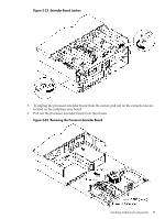
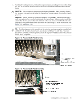
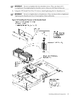
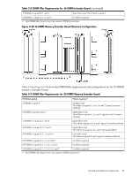
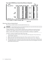
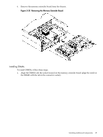
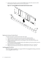
Extender Board Switches and Jumpers The processor extender board includes switches and jumpers. These switches are factory preset and must not be altered except by an HP Service Representative. Replacing the Processor Extender Board To replace the processor extender board, follow these steps: 1. Ensure that the extraction levers are positioned in the outward, unlocked position. 2. Align the processor extender board with the left and right card guides. 3. Slide the processor extender board in until it begins to seat in the socket located on the midplane riser board. 4. Push the extraction levers inward to the locked position in order to fully seat the processor extender board into the midplane riser board socket. 5. Replace the front cover and front bezel. 6. Verify processor operation by using the system utilities. • To verify operation, use the iLO MP commands and the BCH commands. • To exercise the processor, use MAKODIAG provided by the offline diagnostic environment. Installing Memory The standard configuration of HP 9000 rp4410 and rp4440 servers include a 16-DIMM memory extender board. This extender board must contain a minimum of 1 GB of memory (four 256 MB DIMMs loaded in quad 0 [connectors 0A, 0B, 0C, and 0D]). (Figure 3-28) An optional 32-DIMM memory extender board is available to replace the 16-DIMM memory extender board. This extender board must contain a minimum of 1 GB of memory (four 256 MB DIMMs loaded in quad 0 [connectors 0A, 0B, 0C, and 0D]). (Figure 3-29) You can insert additional DIMMs into both 16- and 32-DIMM boards. When adding DIMMs, you must use a minimum of four like-sized DIMMs in the next available quad. Supported DIMM Sizes You can install up to 128 GB of memory in the server. Supported DIMM sizes are as follows: • 256 MB, 512 MB, 1 GB, 2 GB, 4 GB Dissimilar DIMM sizes can be used across the extender board, but all four DIMMs in each quad must match. For cooling purposes, you must install DIMM fillers into unused connectors. DIMM Slot Fillers Both the 16- and 32-DIMM extender boards must have DIMM slot filler boards placed over all unfilled DIMM connectors. As you fill DIMM quads with additional memory, you must remove the DIMM slot fillers covering the connectors. All remaining DIMM fillers in unused connectors must remain in place to maximize internal cooling. NOTE: One DIMM filler board covers two adjacent DIMM connectors. Remove DIMM slot fillers as you add memory and you will always retain the correct configuration. Table 3-8 and Figure 3-28 show the DIMM filler requirements and configuration for the 16-DIMM memory extender board. Table 3-8 DIMM Filler Requirements for 16-DIMM Extender Board DIMMs Loaded Fillers Required1 4 DIMMs in quad 0 Six fillers total: Two fillers each in quads 1, 2, and 3 8 DIMMs in quads 0 and 1 Four fillers total: Two fillers in quads 2 and 3 84 Installing the System
-
 1
1 -
2
-
3
-
4
-
5
-
6
-
7
-
8
-
9
-
10
-
11
-
12
-
13
-
14
-
15
-
16
-
17
-
18
-
19
-
20
-
21
-
22
-
23
-
24
-
25
-
26
-
27
-
28
-
29
-
30
-
31
-
32
-
33
-
34
-
35
-
36
-
37
-
38
-
39
-
40
-
41
-
42
-
43
-
44
-
45
-
46
-
47
-
48
-
49
-
50
-
51
-
52
-
53
-
54
-
55
-
56
-
57
-
58
-
59
-
60
-
61
-
62
-
63
-
64
-
65
-
66
-
67
-
68
-
69
-
70
-
71
-
72
-
73
-
74
-
75
-
76
-
77
-
78
-
 79
79 -
 80
80 -
 81
81 -
 82
82 -
 83
83 -
 84
84 -
 85
85 -
 86
86 -
 87
87 -
 88
88 -
 89
89 -
90
-
91
-
92
-
93
-
94
-
95
-
96
-
97
-
98
-
99
-
100
-
101
-
102
-
103
-
104
-
105
-
106
-
107
-
108
-
109
-
110
-
111
-
112
-
113
-
114
-
115
-
116
-
117
-
118
-
119
-
120
-
121
-
122
-
123
-
124
-
125
-
126
-
127
-
128
-
129
-
130
-
131
-
132
-
133
-
134
-
135
-
136
-
137
-
138
-
139
-
140
-
141
-
142
-
143
-
144
-
145
-
146
-
147
-
148
-
149
-
150
-
151
-
152
-
153
-
154
-
155
-
156
-
157
-
158
-
159
-
160
-
161
-
162
-
163
-
164
-
165
-
166
-
167
-
168
-
169
-
170
-
171
-
172
-
173
-
174
-
175
-
176
-
177
-
178
-
179
-
180
-
181
-
182
-
183
-
184
-
185
-
186
-
187
-
188
-
189
-
190
-
191
-
192
-
193
-
194
-
195
-
196
-
197
-
198
-
199
-
200
-
201
-
202
-
203
-
204
-
205
-
206
-
207
-
208
-
209
-
210
-
211
-
212
-
213
-
214
-
215
-
216
-
217
-
218
-
219
-
220
-
221
-
222
-
223
-
224
-
225
-
226
-
227
-
228
-
229
-
230
-
231
-
232
-
233
-
234
-
235
-
236
-
237
-
238
-
239
-
240
-
241
-
242
-
243
-
244
-
245
-
246
 |
 |
