HP 9000 rp4410-4 User Service Guide, Fifth Edition - HP 9000 rp4410/4440 - Page 184
PCI/PCI-X Card Path Logging
 |
View all HP 9000 rp4410-4 manuals
Add to My Manuals
Save this manual to your list of manuals |
Page 184 highlights
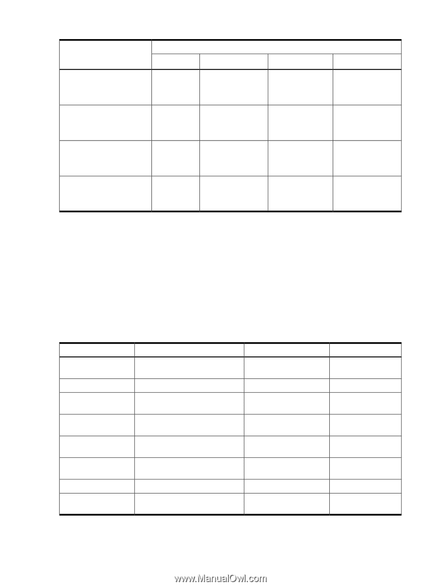
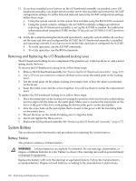
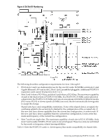
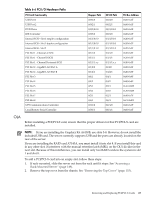
Table 6-4 PCI/PCI-X Card Slot Frequency and Bus Mode Compatibility for Shared Slots1 Current PCI Bus Mode and Cards to be installed Frequency for the Current Card in a Shared Slot PCI 33 MHz PCI 66 MHz PCI-X 66 MHz PCI-X 133 MHz PCI 33 MHz Compatible2 Compatible2 Compatible2 Compatible2 New card running at New card running at New card running at 33 MHz 33 MHz 33 MHz PCI 66 MHz Incompatible frequency3 Compatible2 Compatible2 Compatible2 New card running at New card running at New card running at 66 MHz 66 MHz 66 MHz PCI-X 66 MHz Incompatible Incompatible bus4 frequency3 Compatible2 Compatible2 New card running at New card running at 66 MHz 66 MHz PCI-X 133 MHz5Running at Incompatible Incompatible PCI-X 66 MHz) frequency3 frequency3 Compatible2 Compatible2 New card running at New card running at 66 MHz 66 MHz 1 The conditions described in this table apply only to shared slots (slots 3 and 4 on bus number 2, slots 5 and 6 on bus number 3). Slots 7 and 8 are not shared slots. 2 Compatible: card is accepted and runs at the frequency shown. 3 Incompatible frequency: card does not work. 4 Incompatible bus: Card does not work. The new card does not initialize and powers off. 5 Maximum bus mode and frequency supported on shared slots is PCI-X 66 MHz. PCI/PCI-X Card Path Logging Some PCI/PCI-X failures result in I/O path logging. These paths help to indicate the source of the error and may be included in the error message or logged into console or event logs. Table 6-5 describes the PCI I/O paths for the server. Table 6-5 PCI I/O Paths Slot Slot 1 (core I/O SCSI) Slot 2 (core I/O LAN) Slot 3 Slot 4 Slot 5 Slot 6 Slot 7 Slot 8 (right) Function Associated with Path Location ACPI Path Ultra 160/320 dual-channel SCSI or Leftmost slot (nearest to RAID HBA center of baseboard) 0/1/1/0 Channel A 0/1/1/1 Channel B Single or Dual-port Gigabit LAN 2nd from left 0/1/2 I/O with 66 MHz 64-bit PCI-X card 3rd from left (shared with slot 4) 0/4/1 I/O with 66 MHz 64-bit PCI-X card 4th from left (shared with slot 3) 0/4/2 I/O with 66 MHz 64-bit PCI-X card 5th from left (shared with slot 6) 0/5/1 I/O with 66 MHz 64-bit PCI-X card 6th from left (shared with slot 5) 0/5/2 I/O with 133 MHz 64-bit PCI-X card 7th from left 0/2/1 I/O with 133 MHz 64-bit PCI-X card Right-most slot (nearest to 0/6/1 edge of baseboard) Table 6-6 describes the PCI I/O hardware paths for the server. 184 Removing and Replacing Components
-
 1
1 -
2
-
3
-
4
-
5
-
6
-
7
-
8
-
9
-
10
-
11
-
12
-
13
-
14
-
15
-
16
-
17
-
18
-
19
-
20
-
21
-
22
-
23
-
24
-
25
-
26
-
27
-
28
-
29
-
30
-
31
-
32
-
33
-
34
-
35
-
36
-
37
-
38
-
39
-
40
-
41
-
42
-
43
-
44
-
45
-
46
-
47
-
48
-
49
-
50
-
51
-
52
-
53
-
54
-
55
-
56
-
57
-
58
-
59
-
60
-
61
-
62
-
63
-
64
-
65
-
66
-
67
-
68
-
69
-
70
-
71
-
72
-
73
-
74
-
75
-
76
-
77
-
78
-
79
-
80
-
81
-
82
-
83
-
84
-
85
-
86
-
87
-
88
-
89
-
90
-
91
-
92
-
93
-
94
-
95
-
96
-
97
-
98
-
99
-
100
-
101
-
102
-
103
-
104
-
105
-
106
-
107
-
108
-
109
-
110
-
111
-
112
-
113
-
114
-
115
-
116
-
117
-
118
-
119
-
120
-
121
-
122
-
123
-
124
-
125
-
126
-
127
-
128
-
129
-
130
-
131
-
132
-
133
-
134
-
135
-
136
-
137
-
138
-
139
-
140
-
141
-
142
-
143
-
144
-
145
-
146
-
147
-
148
-
149
-
150
-
151
-
152
-
153
-
154
-
155
-
156
-
157
-
158
-
159
-
160
-
161
-
162
-
163
-
164
-
165
-
166
-
167
-
168
-
169
-
170
-
171
-
172
-
173
-
174
-
175
-
176
-
177
-
178
-
 179
179 -
 180
180 -
 181
181 -
 182
182 -
 183
183 -
 184
184 -
 185
185 -
 186
186 -
 187
187 -
 188
188 -
 189
189 -
190
-
191
-
192
-
193
-
194
-
195
-
196
-
197
-
198
-
199
-
200
-
201
-
202
-
203
-
204
-
205
-
206
-
207
-
208
-
209
-
210
-
211
-
212
-
213
-
214
-
215
-
216
-
217
-
218
-
219
-
220
-
221
-
222
-
223
-
224
-
225
-
226
-
227
-
228
-
229
-
230
-
231
-
232
-
233
-
234
-
235
-
236
-
237
-
238
-
239
-
240
-
241
-
242
-
243
-
244
-
245
-
246
 |
 |