HP 9000 rp4410-4 User Service Guide, Fifth Edition - HP 9000 rp4410/4440 - Page 103
Core I/O Connections, Applying Standby Power to the Server, Connecting to the LAN
 |
View all HP 9000 rp4410-4 manuals
Add to My Manuals
Save this manual to your list of manuals |
Page 103 highlights
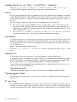
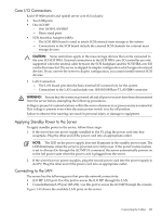
Core I/O Connections Each HP 9000 rp4410 and rp4440 server core I/O includes: • Two USB ports • One iLO MP - One 10/100 LAN-RJ45 - Three serial ports • SCSI Host Bus Adapter (HBA) - The SCSI HBA board is used to attach SCSI external mass storage to the system. - Connections to the SCSI board include the external SCSI channels for external mass storage devices. CAUTION: Some restrictions apply to the mass storage devices that can be connected to the core I/O SCSI HBA. External connections to the SCSI HBA core I/O controller are only supported when the internal cable between the SCSI backplane and the SCSI HBA core I/O card is disconnected. The server is shipped in simplex configuration which supports external devices. If you convert the server to duplex configuration, you cannot install external SCSI devices. • LAN Connection - The LAN board provides the basic external I/O connectivity for the system - Connections to the LAN card include one 10/100/1000 Base-T LAN RJ45 connector WARNING! Ensure that the system is powered off and all power sources have been disconnected from the server before attempting the following procedures. Voltage is present at various locations within the server whenever an ac power source is connected. This voltage is present even when the main power switch is in the off position. Failure to observe this warning can result in personal injury or damage to equipment. Applying Standby Power to the Server To apply standby power to the server, follow these steps: 1. If the server has one power supply installed in slot P1, plug the power cord into that receptacle. Plug the other end of the power cord into an appropriate outlet. NOTE: The LED on the power supply does not illuminate in the standby power state. The LED illuminates when the server is powered on to full power. If the power restore feature is set to Always On through the iLO MP PR command, the server automatically powers on to the full power state when the power cord is plugged into the server. 2. If the server has two power supplies, plug the second power cord into the power supply in slot P2. Plug the other end of the power cord into an appropriate outlet. Connecting to the LAN The server has the following ports that provide network connectivity: • iLO MP LAN port. Use this port to access the iLO MP through the LAN. • Console/Remote/UPS port (RS-232). Use this port to access the iLO MP through the console. Figure 3-40 shows the available LAN ports on the server. Connecting the Cables 103
-
 1
1 -
2
-
3
-
4
-
5
-
6
-
7
-
8
-
9
-
10
-
11
-
12
-
13
-
14
-
15
-
16
-
17
-
18
-
19
-
20
-
21
-
22
-
23
-
24
-
25
-
26
-
27
-
28
-
29
-
30
-
31
-
32
-
33
-
34
-
35
-
36
-
37
-
38
-
39
-
40
-
41
-
42
-
43
-
44
-
45
-
46
-
47
-
48
-
49
-
50
-
51
-
52
-
53
-
54
-
55
-
56
-
57
-
58
-
59
-
60
-
61
-
62
-
63
-
64
-
65
-
66
-
67
-
68
-
69
-
70
-
71
-
72
-
73
-
74
-
75
-
76
-
77
-
78
-
79
-
80
-
81
-
82
-
83
-
84
-
85
-
86
-
87
-
88
-
89
-
90
-
91
-
92
-
93
-
94
-
95
-
96
-
97
-
 98
98 -
 99
99 -
 100
100 -
 101
101 -
 102
102 -
 103
103 -
 104
104 -
 105
105 -
 106
106 -
 107
107 -
 108
108 -
109
-
110
-
111
-
112
-
113
-
114
-
115
-
116
-
117
-
118
-
119
-
120
-
121
-
122
-
123
-
124
-
125
-
126
-
127
-
128
-
129
-
130
-
131
-
132
-
133
-
134
-
135
-
136
-
137
-
138
-
139
-
140
-
141
-
142
-
143
-
144
-
145
-
146
-
147
-
148
-
149
-
150
-
151
-
152
-
153
-
154
-
155
-
156
-
157
-
158
-
159
-
160
-
161
-
162
-
163
-
164
-
165
-
166
-
167
-
168
-
169
-
170
-
171
-
172
-
173
-
174
-
175
-
176
-
177
-
178
-
179
-
180
-
181
-
182
-
183
-
184
-
185
-
186
-
187
-
188
-
189
-
190
-
191
-
192
-
193
-
194
-
195
-
196
-
197
-
198
-
199
-
200
-
201
-
202
-
203
-
204
-
205
-
206
-
207
-
208
-
209
-
210
-
211
-
212
-
213
-
214
-
215
-
216
-
217
-
218
-
219
-
220
-
221
-
222
-
223
-
224
-
225
-
226
-
227
-
228
-
229
-
230
-
231
-
232
-
233
-
234
-
235
-
236
-
237
-
238
-
239
-
240
-
241
-
242
-
243
-
244
-
245
-
246
 |
 |
