HP 9000 rp4410-4 User Service Guide, Fifth Edition - HP 9000 rp4410/4440 - Page 175
I/O Baseboard Assembly, Removing the I/O Baseboard Assembly, Accessing
 |
View all HP 9000 rp4410-4 manuals
Add to My Manuals
Save this manual to your list of manuals |
Page 175 highlights
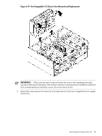
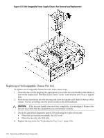
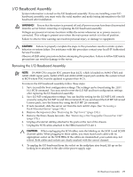
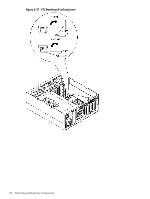
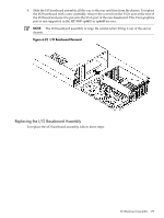
I/O Baseboard Assembly System information is stored on the I/O baseboard assembly. If you are installing a new I/O baseboard assembly, you must write the serial number and model string information to the I/O baseboard after installation. WARNING! Ensure that the system is powered off and all power sources have been disconnected from the server before removing or replacing the I/O baseboard assembly. Voltages are present at various locations within the server whenever an ac power source is connected. This voltage is present even when the main power switch is in the off position. Failure to observe this warning can result in personal injury or damage to equipment. CAUTION: Failure to properly complete the steps in this procedure results in erratic system behavior or system failure. For assistance with this procedure contact your local HP Authorized Service Provider. Observe all ESD safety precautions before attempting this procedure. Failure to follow ESD safety precautions can result in damage to the server. Removing the I/O Baseboard Assembly NOTE: PA 8900 CPUs require PDC greater than 44.21, which is loaded on A6961-67401 and A6961-69401 repair parts. A6961-67301 and A6961-69301 repair parts enables the system to boot to BCH where PDC must be updated to greater than 44.21. To remove the I/O baseboard assembly, follow these steps: 1. Save (record) the boot configuration settings. The settings can be found using the INFO ALL BCH command . You may need to reset the iLO MP and boot configuration settings after replacing the I/O baseboard assembly. 2. Save iLO MP configuration settings. You can find the setting for the iLO MP LAN console access by using the iLO MP LS and DNS commands. If you purchased the iLO MP Advanced Licence pack, save the license key using the iLO MP LM command. 3. If rack-mounted, slide the server out from the rack until it stops. (See "Accessing a Rack-Mounted Server" (page 149).) 4. Remove the top cover. (See "Removing the Top Cover" (page 153).) 5. Remove the three chassis fan units. (See "Removing a Hot-Swappable Chassis Fan Unit" (page 172).) 6. Unplug all external cabling attached to the ports at the rear of the chassis. 7. Unplug the SCSI cables attached to the HBA board in PCI slot 1. CAUTION: When unplugging the SCSI cables, note the labeling on the SCSI A and SCSI B channel cables. When plugging-in these cables, you must match each cable with its appropriate socket on the SCSI HBA. If the cables are mismatched your system may not reboot. Both cables and sockets are clearly marked with the correct channel. 8. To unplug the I/O baseboard from the socket on the midplane riser board, lift up on the locking lever attached to the side of the power supply cage. I/O Baseboard Assembly 175
-
 1
1 -
2
-
3
-
4
-
5
-
6
-
7
-
8
-
9
-
10
-
11
-
12
-
13
-
14
-
15
-
16
-
17
-
18
-
19
-
20
-
21
-
22
-
23
-
24
-
25
-
26
-
27
-
28
-
29
-
30
-
31
-
32
-
33
-
34
-
35
-
36
-
37
-
38
-
39
-
40
-
41
-
42
-
43
-
44
-
45
-
46
-
47
-
48
-
49
-
50
-
51
-
52
-
53
-
54
-
55
-
56
-
57
-
58
-
59
-
60
-
61
-
62
-
63
-
64
-
65
-
66
-
67
-
68
-
69
-
70
-
71
-
72
-
73
-
74
-
75
-
76
-
77
-
78
-
79
-
80
-
81
-
82
-
83
-
84
-
85
-
86
-
87
-
88
-
89
-
90
-
91
-
92
-
93
-
94
-
95
-
96
-
97
-
98
-
99
-
100
-
101
-
102
-
103
-
104
-
105
-
106
-
107
-
108
-
109
-
110
-
111
-
112
-
113
-
114
-
115
-
116
-
117
-
118
-
119
-
120
-
121
-
122
-
123
-
124
-
125
-
126
-
127
-
128
-
129
-
130
-
131
-
132
-
133
-
134
-
135
-
136
-
137
-
138
-
139
-
140
-
141
-
142
-
143
-
144
-
145
-
146
-
147
-
148
-
149
-
150
-
151
-
152
-
153
-
154
-
155
-
156
-
157
-
158
-
159
-
160
-
161
-
162
-
163
-
164
-
165
-
166
-
167
-
168
-
169
-
 170
170 -
 171
171 -
 172
172 -
 173
173 -
 174
174 -
 175
175 -
 176
176 -
 177
177 -
 178
178 -
 179
179 -
 180
180 -
181
-
182
-
183
-
184
-
185
-
186
-
187
-
188
-
189
-
190
-
191
-
192
-
193
-
194
-
195
-
196
-
197
-
198
-
199
-
200
-
201
-
202
-
203
-
204
-
205
-
206
-
207
-
208
-
209
-
210
-
211
-
212
-
213
-
214
-
215
-
216
-
217
-
218
-
219
-
220
-
221
-
222
-
223
-
224
-
225
-
226
-
227
-
228
-
229
-
230
-
231
-
232
-
233
-
234
-
235
-
236
-
237
-
238
-
239
-
240
-
241
-
242
-
243
-
244
-
245
-
246
 |
 |