HP 9000 rp4410-4 User Service Guide, Fifth Edition - HP 9000 rp4410/4440 - Page 179
For PRODUCT NUMBER, enter the appropriate number typically A9956A, A9951A, SER_INIT, reset
 |
View all HP 9000 rp4410-4 manuals
Add to My Manuals
Save this manual to your list of manuals |
Page 179 highlights
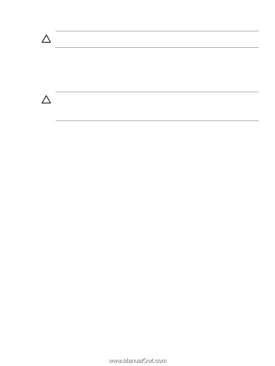
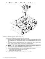
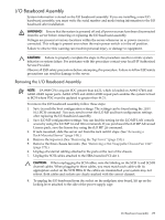
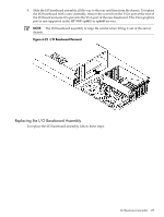
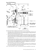
4. Align the I/O baseboard assembly rails with the chassis slots and slide the assembly into the chassis until it stops against the midplane riser board socket. CAUTION: Ensure the I/O baseboard locking lever is in the up position to engage correctly with the midplane riser board socket. 5. With the I/O board flush against the midplane riser board socket, push down firmly on the locking lever until the I/O baseboard plugs all the way into the midplane riser board socket and the locking lever clicks into place on the chassis wall (Figure 6-21). 6. Replace the three chassis fan units. See "Replacing a Hot-Swappable Chassis Fan Unit" (page 174). 7. Plug all external cables into the ports at the rear of the chassis. CAUTION: When plugging the SCSI cables, note the labeling on the SCSI A and SCSI B channel cables. You must match each cable with its appropriate socket on the SCSI HBA. If the cables are mismatched, your system may not reboot. Both cables and sockets are clearly marked with the correct channel. 8. Plug the internal SCSI cables into the HBA board in PCI slot 1. 9. Replace the top cover. See "Replacing the Top Cover" (page 154). 10. Reconnect all power and external cables. 11. Turn on the server. 12. If you have installed a new I/O baseboard assembly, you must write the serial number and model string data to the new I/O board. To write the data to the new board, follow these steps: a. Locate the system serial number and note it for use in the following steps. The system serial number can be found in the following two places: • At the right of the front bezel, above and immediately to the right of the disk drives, locate the pull tab and extend the tab from the server to display product information. A label containing the system serial number is attached to the pull tab. • A label containing the system serial number is located on the right side of the chassis as you face the server. b. Monitor system startup on a terminal. c. To display the service menu, enter the SER command at the BCH prompt. d. To access server information, enter the SER_INIT command. • To enter the original product and serial number, use the SERN command. • For PRODUCT NUMBER, enter the appropriate number (typically A9956A, A9951A, and so on). • For SYSTEM SERIAL NUMBER, enter the serial number from the pull tab or from the side of the chassis. • For MODEL STRING, enter the model string value applicable to your system. Valid choices are as follows: - 9000/800rp4440 PA8800 dc - 9000/800rp4440 PA8900 dc - 9000/800rp4410 PA8900 dc- Max 4 Core - 9000/800rp4410#1 PA8900 dc- 1 Core When prompted for approval, enter y. e. To reset the system, enter the reset command. f. Reset the server time and date, and restore the iLO MP configuration settings as described in the following step. I/O Baseboard Assembly 179
-
 1
1 -
2
-
3
-
4
-
5
-
6
-
7
-
8
-
9
-
10
-
11
-
12
-
13
-
14
-
15
-
16
-
17
-
18
-
19
-
20
-
21
-
22
-
23
-
24
-
25
-
26
-
27
-
28
-
29
-
30
-
31
-
32
-
33
-
34
-
35
-
36
-
37
-
38
-
39
-
40
-
41
-
42
-
43
-
44
-
45
-
46
-
47
-
48
-
49
-
50
-
51
-
52
-
53
-
54
-
55
-
56
-
57
-
58
-
59
-
60
-
61
-
62
-
63
-
64
-
65
-
66
-
67
-
68
-
69
-
70
-
71
-
72
-
73
-
74
-
75
-
76
-
77
-
78
-
79
-
80
-
81
-
82
-
83
-
84
-
85
-
86
-
87
-
88
-
89
-
90
-
91
-
92
-
93
-
94
-
95
-
96
-
97
-
98
-
99
-
100
-
101
-
102
-
103
-
104
-
105
-
106
-
107
-
108
-
109
-
110
-
111
-
112
-
113
-
114
-
115
-
116
-
117
-
118
-
119
-
120
-
121
-
122
-
123
-
124
-
125
-
126
-
127
-
128
-
129
-
130
-
131
-
132
-
133
-
134
-
135
-
136
-
137
-
138
-
139
-
140
-
141
-
142
-
143
-
144
-
145
-
146
-
147
-
148
-
149
-
150
-
151
-
152
-
153
-
154
-
155
-
156
-
157
-
158
-
159
-
160
-
161
-
162
-
163
-
164
-
165
-
166
-
167
-
168
-
169
-
170
-
171
-
172
-
173
-
 174
174 -
 175
175 -
 176
176 -
 177
177 -
 178
178 -
 179
179 -
 180
180 -
 181
181 -
 182
182 -
 183
183 -
 184
184 -
185
-
186
-
187
-
188
-
189
-
190
-
191
-
192
-
193
-
194
-
195
-
196
-
197
-
198
-
199
-
200
-
201
-
202
-
203
-
204
-
205
-
206
-
207
-
208
-
209
-
210
-
211
-
212
-
213
-
214
-
215
-
216
-
217
-
218
-
219
-
220
-
221
-
222
-
223
-
224
-
225
-
226
-
227
-
228
-
229
-
230
-
231
-
232
-
233
-
234
-
235
-
236
-
237
-
238
-
239
-
240
-
241
-
242
-
243
-
244
-
245
-
246
 |
 |