HP 9000 rp4410-4 User Service Guide, Fifth Edition - HP 9000 rp4410/4440 - Page 161
Processor Extender Board, Removing the Processor Extender Board, Accessing
 |
View all HP 9000 rp4410-4 manuals
Add to My Manuals
Save this manual to your list of manuals |
Page 161 highlights
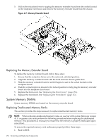
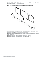
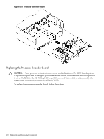
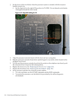
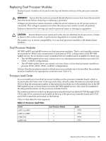
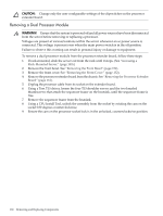
Processor Extender Board The processor extender board is located under the front cover, directly beneath the memory extender board. The processor extender board can hold one to four dual processor modules. WARNING! Ensure that the system is powered off and all power sources have been disconnected from the server before removing or replacing the processor extender board. Voltages are present at various locations within the server whenever an ac power source is connected. This voltage is present even when the main power switch is in the off position. Failure to observe this warning can result in personal injury or damage to equipment. CAUTION: Failure to properly complete the steps in this procedure results in erratic system behavior or system failure. For assistance with this procedure contact your local HP Authorized Service Provider. Observe all ESD safety precautions before attempting this procedure. Failure to follow ESD safety precautions can result in damage to the server. Removing the Processor Extender Board To remove the processor extender board, follow these steps: 1. If rack-mounted, slide the server out from the rack until it stops. See "Accessing a Rack-Mounted Server" (page 149). NOTE: You can remove the processor extender board without removing the server from the rack. 2. Remove the front bezel. See "Removing the Front Bezel" (page 152). 3. Remove the front cover. See "Removing the Front Cover" (page 152). 4. Press the latch on the extraction levers located on each side of the processor extender board. 5. To unplug the processor extender board from the socket located on the midplane riser board, pull out the extraction levers . Processor Extender Board 161
-
 1
1 -
2
-
3
-
4
-
5
-
6
-
7
-
8
-
9
-
10
-
11
-
12
-
13
-
14
-
15
-
16
-
17
-
18
-
19
-
20
-
21
-
22
-
23
-
24
-
25
-
26
-
27
-
28
-
29
-
30
-
31
-
32
-
33
-
34
-
35
-
36
-
37
-
38
-
39
-
40
-
41
-
42
-
43
-
44
-
45
-
46
-
47
-
48
-
49
-
50
-
51
-
52
-
53
-
54
-
55
-
56
-
57
-
58
-
59
-
60
-
61
-
62
-
63
-
64
-
65
-
66
-
67
-
68
-
69
-
70
-
71
-
72
-
73
-
74
-
75
-
76
-
77
-
78
-
79
-
80
-
81
-
82
-
83
-
84
-
85
-
86
-
87
-
88
-
89
-
90
-
91
-
92
-
93
-
94
-
95
-
96
-
97
-
98
-
99
-
100
-
101
-
102
-
103
-
104
-
105
-
106
-
107
-
108
-
109
-
110
-
111
-
112
-
113
-
114
-
115
-
116
-
117
-
118
-
119
-
120
-
121
-
122
-
123
-
124
-
125
-
126
-
127
-
128
-
129
-
130
-
131
-
132
-
133
-
134
-
135
-
136
-
137
-
138
-
139
-
140
-
141
-
142
-
143
-
144
-
145
-
146
-
147
-
148
-
149
-
150
-
151
-
152
-
153
-
154
-
155
-
 156
156 -
 157
157 -
 158
158 -
 159
159 -
 160
160 -
 161
161 -
 162
162 -
 163
163 -
 164
164 -
 165
165 -
 166
166 -
167
-
168
-
169
-
170
-
171
-
172
-
173
-
174
-
175
-
176
-
177
-
178
-
179
-
180
-
181
-
182
-
183
-
184
-
185
-
186
-
187
-
188
-
189
-
190
-
191
-
192
-
193
-
194
-
195
-
196
-
197
-
198
-
199
-
200
-
201
-
202
-
203
-
204
-
205
-
206
-
207
-
208
-
209
-
210
-
211
-
212
-
213
-
214
-
215
-
216
-
217
-
218
-
219
-
220
-
221
-
222
-
223
-
224
-
225
-
226
-
227
-
228
-
229
-
230
-
231
-
232
-
233
-
234
-
235
-
236
-
237
-
238
-
239
-
240
-
241
-
242
-
243
-
244
-
245
-
246
 |
 |