HP 9000 rp4410-4 User Service Guide, Fifth Edition - HP 9000 rp4410/4440 - Page 207
Removing and Replacing Core I/O Cards, Safety Information, Required Service Tools
 |
View all HP 9000 rp4410-4 manuals
Add to My Manuals
Save this manual to your list of manuals |
Page 207 highlights
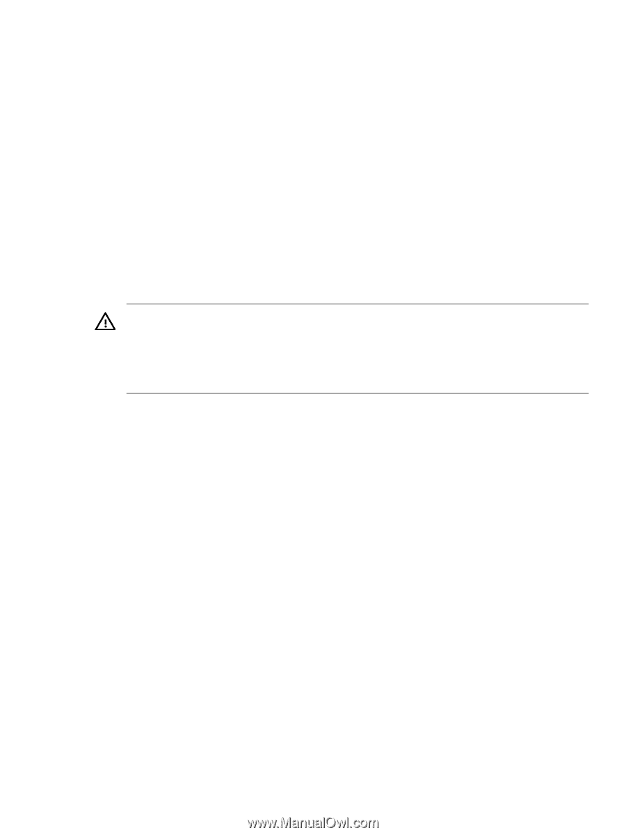
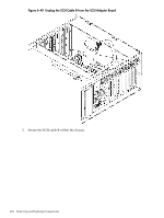
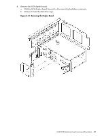
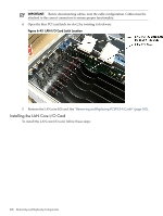
9. Check the SEL for erroneous system events. Removing and Replacing Core I/O Cards The HP 9000 rp4410 and rp4440 servers have two I/O card slots that are dedicated for core I/O cards. Safety Information Use care to prevent injury and equipment damage when performing removal and replacement procedures. Voltages might be present within the server. Many assemblies are sensitive to damage by electrostatic discharge. To prevent harm to both you and the server, follow the procedures listed below to ensure safe handling of components: • Use an antistatic wrist strap and a grounding mat, such as those included in the Electrically Conductive Field Service Grounding Kit (HP part number 9300-1155). • Handle accessory boards and components by the edges only. Do not touch any metal-edge connectors or any electrical components on accessory boards. • Do not wear clothing subject to static charge build-up, such as wool or synthetic materials. WARNING! Ensure that the system is powered off and all power sources have been disconnected from the server before removing and replacing the core I/O cards. Voltages are present at various locations within the server whenever an ac power source is connected. This voltage is present even when the main power switch is in the off position. Failure to observe this warning can result in personal injury or damage to equipment. Required Service Tools Service of this product can require one or more of the following tools: • Electrically Conductive Field Service Kit (HP part number 9300-1155) • 1/4 inch Flat Blade Screwdriver • ACX-15 torx Screwdriver PCI Slot Locations and Configurations PCI slots are numbered from 1 through 8 in the server. The dedicated core I/O card slots are slots 1 and 2. The following describes configuration requirements for slots 1 and 2: • PCI slot 1 is dedicated for use by a SCSI HBA card. Slot 1 is not hot-pluggable. Additional PCI expansion cards cannot be placed in slot 1. • PCI slot 2 is dedicated for use by a LAN card. Slot 2 is not hot-pluggable. Additional PCI expansion cards cannot be placed in slot 2. Removing the LAN Core I/O Card To remove the LAN core I/O card in slot 2, follow these steps: 1. If rack-mounted, slide the server out from the rack until it stops. See "Accessing a Rack-Mounted Server" (page 149). 2. Remove the top cover from the chassis. See "Removing the Top Cover" (page 153). 3. Disconnect any LAN cables connected to the LAN core I/O card. Removing and Replacing Core I/O Cards 207
-
 1
1 -
2
-
3
-
4
-
5
-
6
-
7
-
8
-
9
-
10
-
11
-
12
-
13
-
14
-
15
-
16
-
17
-
18
-
19
-
20
-
21
-
22
-
23
-
24
-
25
-
26
-
27
-
28
-
29
-
30
-
31
-
32
-
33
-
34
-
35
-
36
-
37
-
38
-
39
-
40
-
41
-
42
-
43
-
44
-
45
-
46
-
47
-
48
-
49
-
50
-
51
-
52
-
53
-
54
-
55
-
56
-
57
-
58
-
59
-
60
-
61
-
62
-
63
-
64
-
65
-
66
-
67
-
68
-
69
-
70
-
71
-
72
-
73
-
74
-
75
-
76
-
77
-
78
-
79
-
80
-
81
-
82
-
83
-
84
-
85
-
86
-
87
-
88
-
89
-
90
-
91
-
92
-
93
-
94
-
95
-
96
-
97
-
98
-
99
-
100
-
101
-
102
-
103
-
104
-
105
-
106
-
107
-
108
-
109
-
110
-
111
-
112
-
113
-
114
-
115
-
116
-
117
-
118
-
119
-
120
-
121
-
122
-
123
-
124
-
125
-
126
-
127
-
128
-
129
-
130
-
131
-
132
-
133
-
134
-
135
-
136
-
137
-
138
-
139
-
140
-
141
-
142
-
143
-
144
-
145
-
146
-
147
-
148
-
149
-
150
-
151
-
152
-
153
-
154
-
155
-
156
-
157
-
158
-
159
-
160
-
161
-
162
-
163
-
164
-
165
-
166
-
167
-
168
-
169
-
170
-
171
-
172
-
173
-
174
-
175
-
176
-
177
-
178
-
179
-
180
-
181
-
182
-
183
-
184
-
185
-
186
-
187
-
188
-
189
-
190
-
191
-
192
-
193
-
194
-
195
-
196
-
197
-
198
-
199
-
200
-
201
-
 202
202 -
 203
203 -
 204
204 -
 205
205 -
 206
206 -
 207
207 -
 208
208 -
 209
209 -
 210
210 -
 211
211 -
 212
212 -
213
-
214
-
215
-
216
-
217
-
218
-
219
-
220
-
221
-
222
-
223
-
224
-
225
-
226
-
227
-
228
-
229
-
230
-
231
-
232
-
233
-
234
-
235
-
236
-
237
-
238
-
239
-
240
-
241
-
242
-
243
-
244
-
245
-
246
 |
 |