HP 9000 rp4410-4 User Service Guide, Fifth Edition - HP 9000 rp4410/4440 - Page 91
Hot-Plug Procedures, OLA
 |
View all HP 9000 rp4410-4 manuals
Add to My Manuals
Save this manual to your list of manuals |
Page 91 highlights
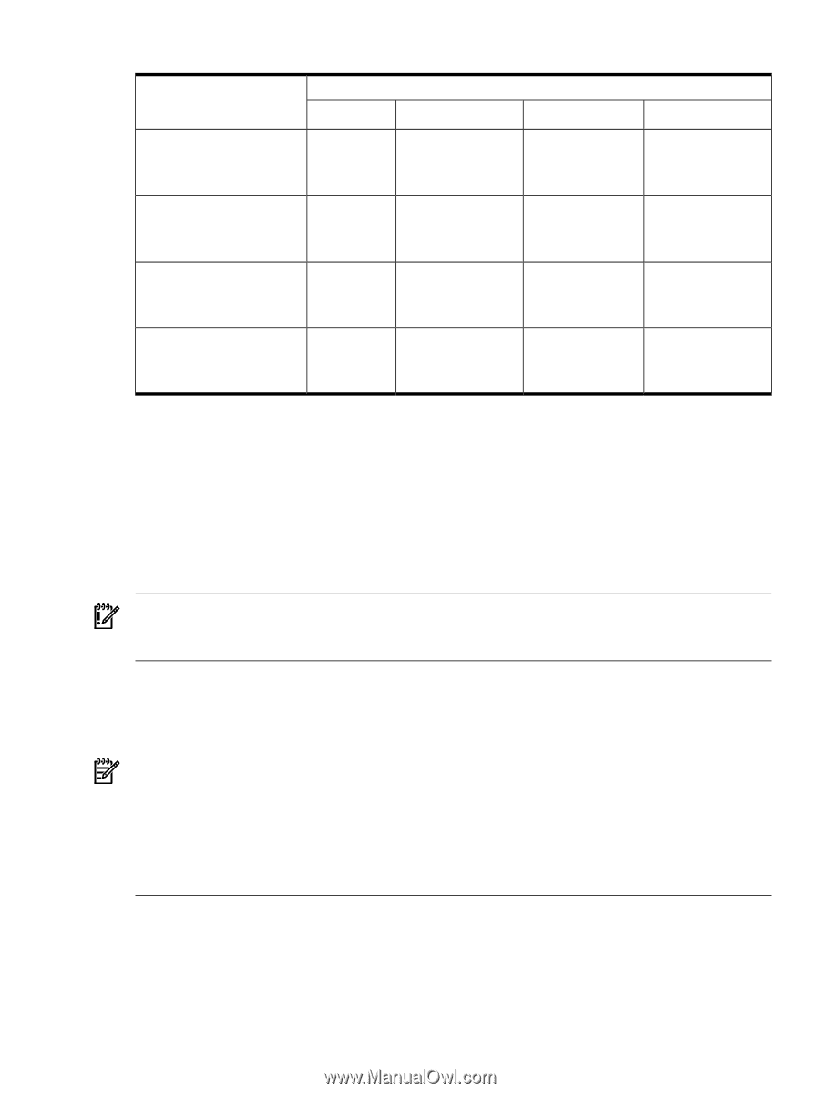
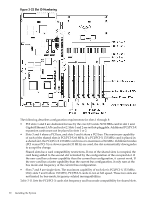
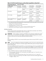
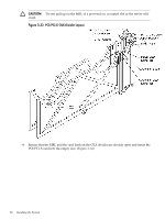
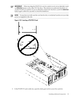
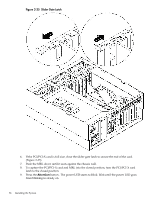
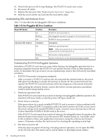
Table 3-11 PCI/PCI-X Card Slot Frequency and Bus Mode Compatibility for Shared Slots1 Current PCI Bus Mode and Cards to be installed Frequency for the Current Card in a Shared Slot PCI 33 MHz PCI 66 MHz PCI-X 66 MHz PCI-X 133 MHz PCI 33 MHz Compatible2 Compatible2 Compatible2 Compatible2 New card running at New card running at New card running at 33 MHz 33 MHz 33 MHz PCI 66 MHz Incompatible frequency3 Compatible2 Compatible2 Compatible2 New card running at New card running at New card running at 66 MHz 66 MHz 66 MHz PCI-X 66 MHz Incompatible Incompatible bus4 frequency3 Compatible2 Compatible2 New card running at New card running at 66 MHz 66 MHz PCI-X 133 MHz5Running at Incompatible Incompatible PCI-X 66 MHz) frequency3 frequency3 Compatible2 Compatible2 New card running at New card running at 66 MHz 66 MHz 1 The conditions described in this table apply only to shared slots (slots 3 and 4 on bus number 2, slots 5 and 6 on bus number 3). Slots 7 and 8 are not shared slots. 2 Compatible: card is accepted and runs at the frequency shown. 3 Incompatible frequency: card does not work. 4 Incompatible bus: Card does not work. The new card does not initialize and powers off. 5 Maximum bus mode and frequency supported on shared slots is PCI-X 66 MHz. Hot-Plug Procedures The hot-plug procedures described in this section use the hardware interface only. Software interface procedures are described in Table 3-10 (page 89). IMPORTANT: Before adding or replacing a PCI/PCI-X card, determine whether that card is critical to the server operation. If you replace a card that is still operating and it is a critical resource to the server, you can cause undesired system downtime. OLA Before installing a PCI/PCI-X card, ensure that the proper drivers for that PCI/PCI-X card are installed. NOTE: If you are installing the Graphics Kit A6150B, use slots 3-8. However, DO NOT install the included USB card. The server currently supports USB and the ports are already located on the rear of the server. If you are installing the RAID card A7143A, you must install it into slot 8. If you install this card in any other slot, it interferes with the manual retention latch (MRL) on the OLX divider in the next slot. Because of this interference, you can install only two RAID cards in the server in slot 1 and slot 8. To add a PCI/PCI-X card into an empty slot, follow these steps: 1. If rack-mounted, slide the server out from the rack until it stops. See "Extend the Server from the Rack" (page 58). 2. Remove the top cover from the chassis. (See "Removing the Top Cover" (page 65).) 3. Choose an empty slot and pull up on the MRL located on the OLX divider approximately 75 degrees. (Figure 3-33) Installing Additional Components 91
-
 1
1 -
2
-
3
-
4
-
5
-
6
-
7
-
8
-
9
-
10
-
11
-
12
-
13
-
14
-
15
-
16
-
17
-
18
-
19
-
20
-
21
-
22
-
23
-
24
-
25
-
26
-
27
-
28
-
29
-
30
-
31
-
32
-
33
-
34
-
35
-
36
-
37
-
38
-
39
-
40
-
41
-
42
-
43
-
44
-
45
-
46
-
47
-
48
-
49
-
50
-
51
-
52
-
53
-
54
-
55
-
56
-
57
-
58
-
59
-
60
-
61
-
62
-
63
-
64
-
65
-
66
-
67
-
68
-
69
-
70
-
71
-
72
-
73
-
74
-
75
-
76
-
77
-
78
-
79
-
80
-
81
-
82
-
83
-
84
-
85
-
 86
86 -
 87
87 -
 88
88 -
 89
89 -
 90
90 -
 91
91 -
 92
92 -
 93
93 -
 94
94 -
 95
95 -
 96
96 -
97
-
98
-
99
-
100
-
101
-
102
-
103
-
104
-
105
-
106
-
107
-
108
-
109
-
110
-
111
-
112
-
113
-
114
-
115
-
116
-
117
-
118
-
119
-
120
-
121
-
122
-
123
-
124
-
125
-
126
-
127
-
128
-
129
-
130
-
131
-
132
-
133
-
134
-
135
-
136
-
137
-
138
-
139
-
140
-
141
-
142
-
143
-
144
-
145
-
146
-
147
-
148
-
149
-
150
-
151
-
152
-
153
-
154
-
155
-
156
-
157
-
158
-
159
-
160
-
161
-
162
-
163
-
164
-
165
-
166
-
167
-
168
-
169
-
170
-
171
-
172
-
173
-
174
-
175
-
176
-
177
-
178
-
179
-
180
-
181
-
182
-
183
-
184
-
185
-
186
-
187
-
188
-
189
-
190
-
191
-
192
-
193
-
194
-
195
-
196
-
197
-
198
-
199
-
200
-
201
-
202
-
203
-
204
-
205
-
206
-
207
-
208
-
209
-
210
-
211
-
212
-
213
-
214
-
215
-
216
-
217
-
218
-
219
-
220
-
221
-
222
-
223
-
224
-
225
-
226
-
227
-
228
-
229
-
230
-
231
-
232
-
233
-
234
-
235
-
236
-
237
-
238
-
239
-
240
-
241
-
242
-
243
-
244
-
245
-
246
 |
 |